Toyota 4Runner: Navigation Receiver Assembly Communication Stop Mode
DESCRIPTION
|
Detection Item |
Symptom |
Trouble Area |
|---|---|---|
|
Navigation Receiver Assembly Communication Stop Mode |
Either condition is met:
|
|
HINT:
For vehicles with a navigation receiver assembly only.
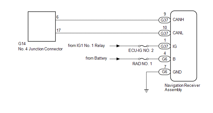
WIRING DIAGRAM
CAUTION / NOTICE / HINT
NOTICE:
Inspect the fuses for circuits related to this system before performing the following inspection procedure.
HINT:
Operating the ignition switch, any switches or any doors triggers related ECU and sensor communication with the CAN, which causes resistance variation.
PROCEDURE
|
1. |
DISCONNECT CABLE FROM NEGATIVE BATTERY TERMINAL |
(a) Disconnect the cable from the negative (-) battery terminal before measuring the resistances of the main wire and branch wire.
CAUTION:
Wait at least 90 seconds after disconnecting the cable from the negative (-) battery terminal to disable the SRS system.
NOTICE:
When disconnecting the cable, some systems need to be initialized after the cable
is reconnected (See page .gif) ).
).
|
.gif)
|
2. |
CHECK FOR OPEN IN CAN BUS WIRE (NAVIGATION RECEIVER ASSEMBLY BRANCH WIRE) |
|
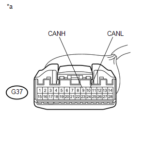
(a) Disconnect the G37 navigation receiver assembly connector. |
|
(b) Measure the resistance according to the value(s) in the table below.
Standard Resistance:
|
Tester Connection |
Switch Condition |
Specified Condition |
|---|---|---|
|
G37-9 (CANH) - G37-10 (CANL) |
Ignition switch off |
54 to 69 Ω |
|
*a |
Front view of wire harness connector (to Navigation Receiver Assembly) |
| NG | .gif) |
REPAIR OR REPLACE NAVIGATION RECEIVER ASSEMBLY BRANCH WIRE OR CONNECTOR (CANH, CANL) |
|
|
3. |
CHECK HARNESS AND CONNECTOR (NAVIGATION RECEIVER ASSEMBLY - BATTERY AND BODY GROUND) |
|
(a) Connect the cable to the negative (-) battery terminal. NOTICE: When disconnecting the cable, some systems need to be initialized after
the cable is reconnected (See page |
|
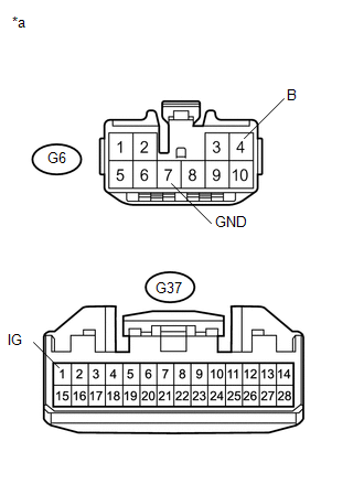
(b) Disconnect the G6 and G37 navigation receiver assembly connectors.
(c) Measure the resistance according to the value(s) in the table below.
Standard Resistance:
|
Tester Connection |
Condition |
Specified Condition |
|---|---|---|
|
G6-7 (GND) - Body ground |
Always |
Below 1 Ω |
(d) Measure the voltage according to the value(s) in the table below.
Standard Voltage:
|
Tester Connection |
Condition |
Specified Condition |
|---|---|---|
|
G37-1 (IG) - Body ground |
Ignition switch ON |
11 to 14 V |
|
G6-4 (B) - Body ground |
Always |
11 to 14 V |
|
*a |
Front view of wire harness connector (to Navigation Receiver Assembly) |
| OK | |
REPLACE NAVIGATION RECEIVER ASSEMBLY |
| NG | |
REPAIR OR REPLACE HARNESS OR CONNECTOR |
 Suspension Control ECU Communication Stop Mode
DESCRIPTION
Detection Item
Symptom
Trouble Area
Suspension Control ECU Communication Stop Mode
Either condition is met:
&quo ...
 Audio Receiver Assembly Communication Stop Mode
DESCRIPTION
Detection Item
Symptom
Trouble Area
Audio Receiver Assembly Communication Stop Mode
Either condition is met:
&qu ...
Other materials about Toyota 4Runner:
System Description
SYSTEM DESCRIPTION
1. AUTOMATIC LIGHT CONTROL SYSTEM
(a) General
When the headlight dimmer switch is in the AUTO position, the automatic light
control sensor detects ambient light levels and outputs a signal to the main body
ECU (multiplex network body ...
Vsc Off Switch
Components
COMPONENTS
ILLUSTRATION
Removal
REMOVAL
PROCEDURE
1. REMOVE DRIVE MONITOR SWITCH
2. REMOVE MAP LIGHT ASSEMBLY
3. REMOVE VSC OFF SWITCH
(a) Disconnect the 2 connectors.
...
0.0197