Toyota 4Runner: Rear Power Outlet Socket
Components
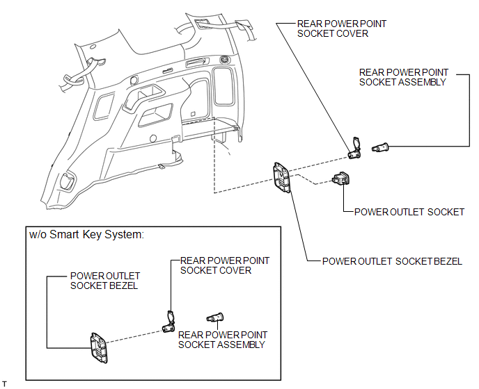
COMPONENTS
ILLUSTRATION
Removal
REMOVAL
PROCEDURE
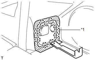
1. REMOVE POWER OUTLET SOCKET BEZEL (w/o Smart Key System)
|
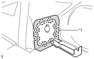
(a) Put protective tape around the power outlet socket bezel. Text in Illustration
|
|
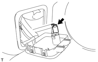
(b) Using a moulding remover, detach the 8 claws and remove the bezel.
|
(c) Disconnect the connector. |
|
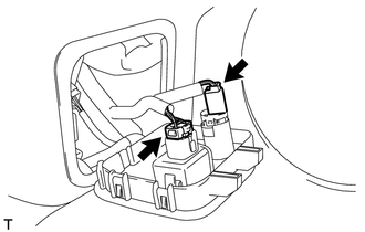
2. REMOVE REAR POWER POINT SOCKET ASSEMBLY (w/o Smart Key System)
|
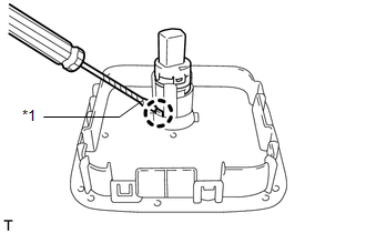
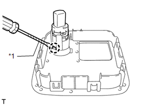
(a) Using a screwdriver, detach the claw and remove the power point socket. HINT: Tape the screwdriver tip before use. Text in Illustration
|
|
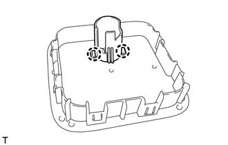
3. REMOVE REAR POWER POINT SOCKET COVER (w/o Smart Key System)
|
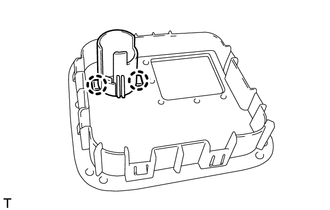
(a) Detach the 2 claws and remove the socket cover. |
|
4. REMOVE POWER OUTLET SOCKET BEZEL (w/ Smart Key System)
|
(a) Put protective tape around the power outlet socket bezel. Text in Illustration
|
|
(b) Using a moulding remover, detach the 8 claws and remove the bezel.
|
(c) Disconnect the 2 connectors. |
|
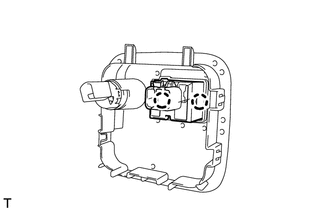
5. REMOVE POWER OUTLET SOCKET (w/ Smart Key System)
|
(a) Detach the 2 claws and remove the socket. |
|
6. REMOVE REAR POWER POINT SOCKET ASSEMBLY (w/ Smart Key System)
|
(a) Using a screwdriver, detach the claw and remove the power point socket. HINT: Tape the screwdriver tip before use. Text in Illustration
|
|
7. REMOVE REAR POWER POINT SOCKET COVER (w/ Smart Key System)
|
(a) Detach the 2 claws and remove the socket cover. |
|
Installation
INSTALLATION
PROCEDURE
1. INSTALL REAR POWER POINT SOCKET COVER (w/o Smart Key System)
(a) Attach the 2 claws to install the socket cover.
2. INSTALL REAR POWER POINT SOCKET ASSEMBLY (w/ Smart Key System)
(a) Attach the claw to install the power point socket.
3. INSTALL POWER OUTLET SOCKET (w/ Smart Key System)
(a) Attach the 2 claws to install the socket.
4. INSTALL POWER OUTLET SOCKET BEZEL (w/ Smart Key System)
(a) Connect the 2 connectors.
(b) Attach the 8 claws to install the bezel.
5. INSTALL REAR POWER POINT SOCKET ASSEMBLY (w/o Smart Key System)
(a) Attach the claw to install the power point socket.
6. INSTALL POWER OUTLET SOCKET BEZEL (w/o Smart Key System)
(a) Connect the connector.
(b) Attach the 8 claws to install the bezel.
7. INSTALL REAR POWER POINT SOCKET COVER (w/ Smart Key System)
(a) Attach the 2 claws to install the socket cover.
 Installation
INSTALLATION
PROCEDURE
1. INSTALL POWER OUTLET SOCKET COVER
(a) Attach the 2 claws to install the socket cover.
2. INSTALL POWER OUTLET SOCKET ASSEMBLY
(a) Attach the claw to install the power ou ...
 Voltage Inverter
...
Other materials about Toyota 4Runner:
Navigation Receiver
Components
COMPONENTS
ILLUSTRATION
Removal
REMOVAL
PROCEDURE
1. DISCONNECT CABLE FROM NEGATIVE BATTERY TERMINAL
CAUTION:
Wait at least 90 seconds after disconnecting the cable from the negative (-)
battery terminal to disable the SRS system.
N ...
Installation
INSTALLATION
CAUTION / NOTICE / HINT
HINT:
Use the same procedure for the RH and LH sides.
The procedure listed below is for the LH side.
When installing the window frame moulding, black out tape and outside
stripe, heat the vehicle body ...
0.0143