Toyota 4Runner: Back Sonar Sensor RH Circuit
DESCRIPTION
The ultrasonic sensor sends and receives ultrasonic waves. Based on the received wave, the sensor calculates the approximate distance between the vehicle and the obstacle, and sends the distance value as a signal to the clearance warning ECU assembly.
WIRING DIAGRAM
PROCEDURE
|
1. |
INSPECT NO. 1 ULTRASONIC SENSOR (REAR CENTER SENSOR RH) |
(a) Remove the No. 1 ultrasonic sensor (rear center sensor RH) (See page
.gif) ).
).
(b) Inspect the No. 1 ultrasonic sensor (rear center sensor RH) (See page
).
| NG | .gif) |
REPLACE NO. 1 ULTRASONIC SENSOR (REAR CENTER SENSOR RH) |
|
.gif)
|
2. |
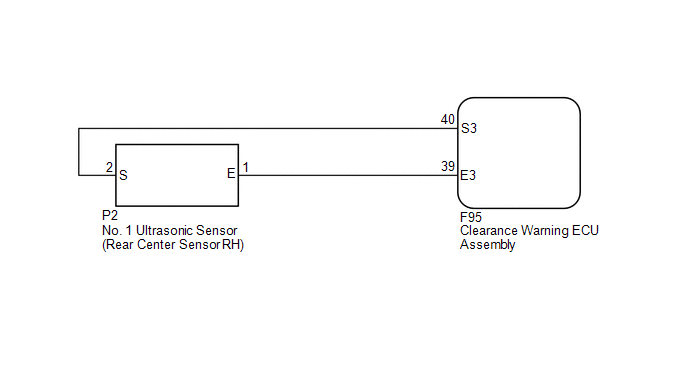
CHECK HARNESS AND CONNECTOR (REAR CENTER SENSOR RH - CLEARANCE WARNING ECU ASSEMBLY) |
(a) Disconnect the P2 No. 1 ultrasonic sensor (rear center sensor RH) connector.
(b) Disconnect the F95 clearance warning ECU assembly connector.
(c) Measure the resistance according to the value(s) in the table below.
Standard Resistance:
|
Tester Connection |
Condition |
Specified Condition |
|---|---|---|
|
P2-1 (E) - F95-39 (E3) |
Always |
Below 1 Ω |
|
P2-2 (S) - F95-40 (S3) |
Always |
Below 1 Ω |
|
P2-1 (E) - Body ground |
Always |
10 kΩ or higher |
|
P2-2 (S) - Body ground |
Always |
10 kΩ or higher |
| OK | |
PROCEED TO NEXT SUSPECTED AREA SHOWN IN PROBLEM SYMPTOMS TABLE |
| NG | |
REPAIR OR REPLACE HARNESS OR CONNECTOR |
 Back Sonar Sensor LH Circuit
DESCRIPTION
The ultrasonic sensor sends and receives ultrasonic waves. Based on the received
wave, the sensor calculates the approximate distance between the vehicle and the
obstacle, and sends t ...
 Front Clearance Sonar Sensor LH Circuit
DESCRIPTION
The ultrasonic sensor sends and receives ultrasonic waves. Based on the received
wave, the sensor calculates the approximate distance between the vehicle and the
obstacle, and sends t ...
Other materials about Toyota 4Runner:
Inspection
INSPECTION
PROCEDURE
1. INSPECT WINDSHIELD WIPER SWITCH ASSEMBLY
(a) Measure the resistance according to the value(s) in the table below.
Standard Resistance:
Front Wiper Switch
Tester Connection
Switch ...
Dtc Check / Clear
DTC CHECK / CLEAR
1. DTC CHECK / CLEAR (when Using Techstream)
(a) Check for DTCs.
(1) Connect the Techstream to the DLC3.
(2) Turn the ignition switch to ON.
(3) Turn the Techstream on.
(4) Enter the following menus: Chassis / ABS/VSC/TRAC / Trouble Cod ...
0.0263