Toyota 4Runner: Clearance Sonar Main Switch Circuit
DESCRIPTION
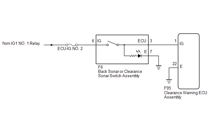
When the back sonar or clearance sonar switch assembly turns on, the on signal is input into the clearance warning ECU assembly.
WIRING DIAGRAM
CAUTION / NOTICE / HINT
NOTICE:
Inspect the fuses for circuits related to this system before performing the following inspection procedure.
PROCEDURE
|
1. |
INSPECT BACK SONAR OR CLEARANCE SONAR SWITCH ASSEMBLY |
(a) Remove the back sonar or clearance sonar switch assembly (See page
.gif) ).
).
(b) Inspect the back sonar or clearance sonar switch assembly (See page
).
| NG | .gif) |
REPLACE BACK SONAR OR CLEARANCE SONAR SWITCH ASSEMBLY |
|
.gif)
|
2. |
CHECK HARNESS AND CONNECTOR (BACK SONAR OR CLEARANCE SONAR SWITCH ASSEMBLY - BATTERY AND BODY GROUND) |
|
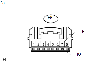
(a) Disconnect the F6 back sonar or clearance sonar switch assembly connector. |
|
(b) Measure the voltage according to the value(s) in the table below.
Standard Voltage:
|
Tester Connection |
Switch Condition |
Specified Condition |
|---|---|---|
|
F6-6 (IG) - Body ground |
Ignition switch ON |
11 to 14 V |
|
Ignition switch off |
Below 1 V |
(c) Measure the resistance according to the value(s) in the table below.
Standard Resistance:
|
Tester Connection |
Condition |
Specified Condition |
|---|---|---|
|
F6-7 (E) - Body ground |
Always |
Below 1 Ω |
|
*a |
Front view of wire harness connector (to Back Sonar or Clearance Sonar Switch Assembly) |
| NG | |
REPAIR OR REPLACE HARNESS OR CONNECTOR |
|
|
3. |
CHECK HARNESS AND CONNECTOR (BACK SONAR OR CLEARANCE SONAR SWITCH ASSEMBLY - CLEARANCE WARNING ECU ASSEMBLY) |
(a) Disconnect the F6 back sonar or clearance sonar switch assembly connector.
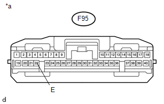
(b) Disconnect the F95 clearance warning ECU assembly connector.
(c) Measure the resistance according to the value(s) in the table below.
Standard Resistance:
|
Tester Connection |
Condition |
Specified Condition |
|---|---|---|
|
F6-3 (ECU) - F95-1 (IG) |
Always |
Below 1 Ω |
|
F6-3 (ECU) - Body ground |
Always |
10 kΩ or higher |
| NG | |
REPAIR OR REPLACE HARNESS OR CONNECTOR |
|
|
4. |
CHECK HARNESS AND CONNECTOR (CLEARANCE WARNING ECU ASSEMBLY - BODY GROUND) |
|
(a) Disconnect the F95 clearance warning ECU assembly connector. |
|
(b) Measure the resistance according to the value(s) in the table below.
Standard Resistance:
|
Tester Connection |
Condition |
Specified Condition |
|---|---|---|
|
F95-22 (E) - Body ground |
Always |
Below 1 Ω |
|
*a |
Front view of wire harness connector (to Clearance Warning ECU Assembly) |
| OK | |
PROCEED TO NEXT SUSPECTED AREA SHOWN IN PROBLEM SYMPTOMS TABLE |
| NG | |
REPAIR OR REPLACE HARNESS OR CONNECTOR |
 Rear Clearance Sonar Sensor RH Circuit
DESCRIPTION
The ultrasonic sensor sends and receives ultrasonic waves. Based on the received
wave, the sensor calculates the approximate distance between the vehicle and the
obstacle, and sends t ...
 Clearance Warning Buzzer Circuit
DESCRIPTION
The clearance warning buzzer sounds to alert the driver. The sounding pattern
changes depending on the distance to an obstacle.
WIRING DIAGRAM
PROCEDURE
1.
C ...
Other materials about Toyota 4Runner:
Terminals Of Ecu
TERMINALS OF ECU
1. CHECK DRIVER SIDE JUNCTION BLOCK ASSEMBLY AND MAIN BODY ECU (MULTIPLEX NETWORK
BODY ECU)
(a) Remove the main body ECU (multiplex network body ECU) (See page
).
(b) Measure the voltage and resistance according to the value(s) in the ...
Dtc Check / Clear
DTC CHECK / CLEAR
HINT:
When using the Techstream with the engine switch off to troubleshoot:
Connect the Techstream to the vehicle and turn a courtesy light switch on
and off at 1.5 second intervals until communication between the Techstream ...
0.008