Toyota 4Runner: Rear Clearance Sonar Sensor RH Circuit
DESCRIPTION
The ultrasonic sensor sends and receives ultrasonic waves. Based on the received wave, the sensor calculates the approximate distance between the vehicle and the obstacle, and sends the distance value as a signal to the clearance warning ECU assembly.
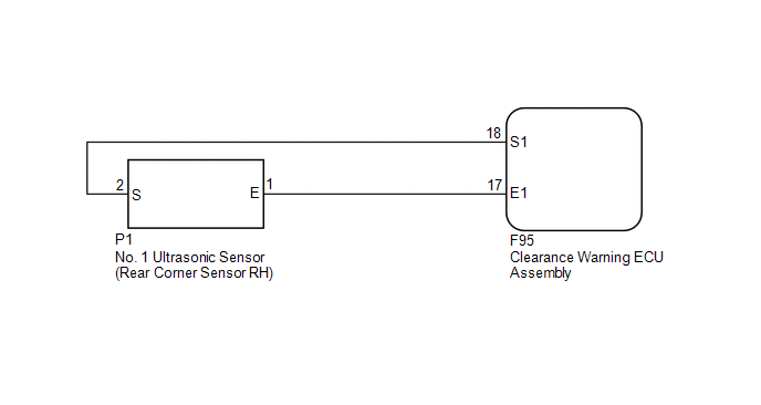
WIRING DIAGRAM
PROCEDURE
|
1. |
REPLACE NO. 1 ULTRASONIC SENSOR (REAR CORNER SENSOR RH) |
(a) Remove the No. 1 ultrasonic sensor (rear corner sensor RH) (See page
.gif) ).
).
(b) Inspect the No. 1 ultrasonic sensor (rear corner sensor RH) (See page
).
| NG | .gif) |
REPLACE NO. 1 ULTRASONIC SENSOR (REAR CORNER SENSOR RH) |
|
.gif)
|
2. |
CHECK HARNESS AND CONNECTOR (REAR CORNER SENSOR RH - CLEARANCE WARNING ECU ASSEMBLY) |
(a) Disconnect the P1 No. 1 ultrasonic sensor (rear corner sensor RH) connector.
(b) Disconnect the F95 clearance warning ECU assembly connector.
(c) Measure the resistance according to the value(s) in the table below.
Standard Resistance:
|
Tester Connection |
Condition |
Specified Condition |
|---|---|---|
|
P1-1 (E) - F95-17 (E1) |
Always |
Below 1 Ω |
|
P1-2 (S) - F95-18 (S1) |
Always |
Below 1 Ω |
|
P1-1 (E) - Body ground |
Always |
10 kΩ or higher |
|
P1-2 (S) - Body ground |
Always |
10 kΩ or higher |
| OK | |
PROCEED TO NEXT SUSPECTED AREA SHOWN IN PROBLEM SYMPTOMS TABLE |
| NG | |
REPAIR OR REPLACE HARNESS OR CONNECTOR |
 Rear Clearance Sonar Sensor LH Circuit
DESCRIPTION
The ultrasonic sensor sends and receives ultrasonic waves. Based on the received
wave, the sensor calculates the approximate distance between the vehicle and the
obstacle, and sends t ...
 Clearance Sonar Main Switch Circuit
DESCRIPTION
When the back sonar or clearance sonar switch assembly turns on, the on signal
is input into the clearance warning ECU assembly.
WIRING DIAGRAM
CAUTION / NOTICE / HINT
NOTICE:
Ins ...
Other materials about Toyota 4Runner:
Problem Symptoms Table
PROBLEM SYMPTOMS TABLE
HINT:
Use the table below to help determine the cause of problem symptoms.
If multiple suspected areas are listed, the potential causes of the symptoms
are listed in order of probability in the "Suspected Area" ...
Diagnostic Trouble Code Chart
DIAGNOSTIC TROUBLE CODE CHART
HINT:
If a trouble code is output during the DTC check, inspect the trouble areas listed
for that code. For details of the code, refer to the "See page" below.
Lighting System
DTC Code
Detecti ...
0.0093