Toyota 4Runner: Clearance Warning Ecu
Components
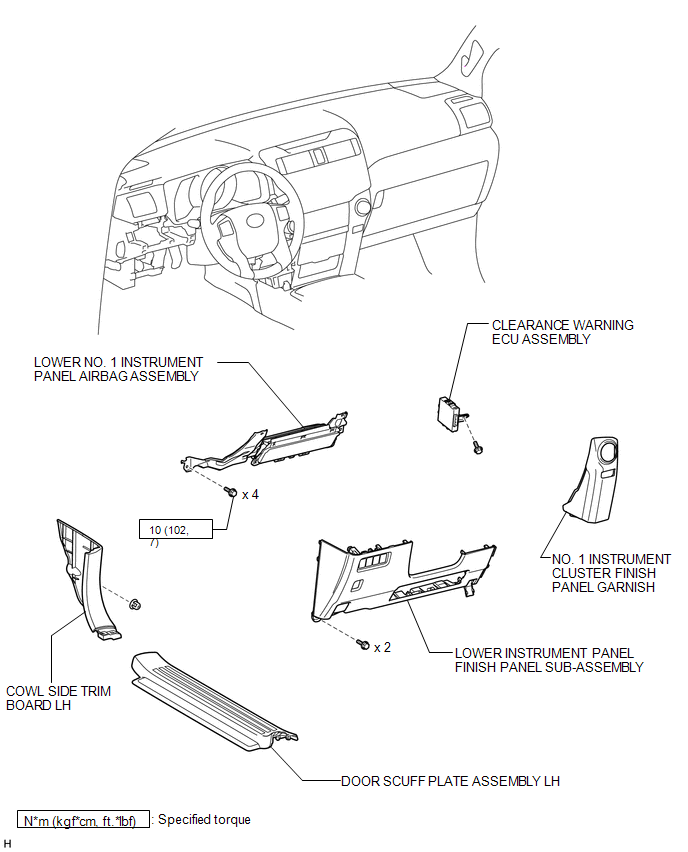
COMPONENTS
ILLUSTRATION
Removal
REMOVAL
PROCEDURE
1. DISCONNECT CABLE FROM NEGATIVE BATTERY TERMINAL
CAUTION:
Wait at least 90 seconds after disconnecting the cable from the negative (-) battery terminal to disable the SRS system.
NOTICE:
When disconnecting the cable, some systems need to be initialized after the cable
is reconnected (See page .gif) ).
).
2. REMOVE DOOR SCUFF PLATE ASSEMBLY LH
3. REMOVE COWL SIDE TRIM BOARD LH
4. REMOVE NO. 1 INSTRUMENT CLUSTER FINISH PANEL GARNISH
5. REMOVE LOWER INSTRUMENT PANEL FINISH PANEL SUB-ASSEMBLY
6. REMOVE LOWER NO. 1 INSTRUMENT PANEL AIRBAG ASSEMBLY
7. REMOVE CLEARANCE WARNING ECU ASSEMBLY
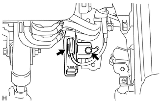
(a) Disconnect the connector.
(b) Remove the bolt and clearance warning ECU.
Installation
INSTALLATION
CAUTION / NOTICE / HINT
HINT:
A bolt without a torque specification is shown in the standard bolt chart (See
page .gif) ).
).
PROCEDURE
1. INSTALL CLEARANCE WARNING ECU ASSEMBLY
(a) Install the clearance warning ECU with the bolt.
(b) Connect the connector.
2. INSTALL LOWER NO. 1 INSTRUMENT PANEL AIRBAG ASSEMBLY
3. INSTALL LOWER INSTRUMENT PANEL FINISH PANEL SUB-ASSEMBLY
4. INSTALL NO. 1 INSTRUMENT CLUSTER FINISH PANEL GARNISH
5. INSTALL COWL SIDE TRIM BOARD LH
6. INSTALL DOOR SCUFF PLATE ASSEMBLY LH
7. CONNECT CABLE TO NEGATIVE BATTERY TERMINAL
NOTICE:
When disconnecting the cable, some systems need to be initialized after the cable
is reconnected (See page ).
8. CHECK SRS WARNING LIGHT
(a) Check the SRS warning light (See page ).
 Clearance Warning Buzzer
Components
COMPONENTS
ILLUSTRATION
Removal
REMOVAL
PROCEDURE
1. REMOVE INSTRUMENT PANEL SUB-ASSEMBLY
(a) Remove the instrument panel sub-assembly (See page
).
2. REMOVE NO. 1 CLEARANCE ...

Other materials about Toyota 4Runner:
System Diagram
SYSTEM DIAGRAM
Communication Table
Transmitting ECU
(Transmitter)
Receiving ECU
(Receiver)
Signal
Line
ECM
Power management control ECU
Crankshaft position sensor signa ...
Back Camera Disconnected (C1622)
DESCRIPTION
This DTC is stored if the navigation receiver assembly judges that the signals
or signal lines between the navigation receiver assembly, and the rear television
camera assembly are not normal as a result of its self check.
DTC No.
...
0.0269