Toyota 4Runner: Diagnosis System
DIAGNOSIS SYSTEM
1. SYMPTOM SIMULATION
HINT:
The most difficult case in troubleshooting is when no problem symptoms occur. In such a case, a thorough problem analysis must be carried out. A simulation of the same or similar conditions and environment in which the problem occurred in the customer's vehicle should be carried out. No matter how much skill or experience a technician has, troubleshooting without confirming the problem symptoms will lead to important repairs being overlooked and mistakes or delays.
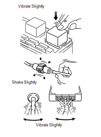
(a) Vibration method: When vibration seems to be the major cause.
HINT:
Perform the simulation method only during the primary check period (for approximately 6 seconds after the ignition switch is turned to ON).
(1) Slightly vibrate the part of the sensor considered to be the cause of the problem with your fingers and check whether the malfunction occurs.
NOTICE:
Shaking the relays too strongly may result in open relays.
(2) Slightly shake the connector vertically and horizontally.
(3) Slightly shake the wire harness vertically and horizontally.
HINT:
The connector joint and fulcrum of the vibration are the major areas to be checked thoroughly.
2. FUNCTION OF SRS WARNING LIGHT
(a) Primary check.
(1) Turn the ignition switch off. Wait for at least 2 seconds, and then turn the ignition switch to ON. The SRS warning light comes on for approximately 6 seconds and diagnosis of the airbag system (including the seat belt pretensioners) is performed.
HINT:
If trouble is detected during the primary check, the SRS warning light remains on even after the primary check period (of approximately 6 seconds) has elapsed.
(b) Constant check.
(1) After the primary check, the center airbag sensor constantly monitors the airbag system for trouble.
HINT:
If trouble is detected during the constant check, the center airbag sensor functions as follows:
- The SRS warning light comes on.
- The SRS warning light goes off, and then comes on. This blinking pattern indicates a source voltage drop. The SRS warning light goes off 10 seconds after the source voltage returns to normal.
(c) Review.
(1) When the airbag system is normal:
The SRS warning light comes on only during the primary check period (for approximately 6 seconds after the ignition switch is turned to ON).
(2) When the airbag system has trouble:
- The SRS warning light remains on even after the primary check period has elapsed.
- The SRS warning light goes off after the primary check, but comes on again during the constant check.
- The SRS warning light does not come on when turning the ignition switch from off to ON.
HINT:
The center airbag sensor functions to keep the SRS warning light on if the airbag has been deployed.
3. CHECK SRS WARNING LIGHT
(a) Turn the ignition switch to ON and check that the SRS warning light comes on for approximately 6 seconds (primary check).
(b) Check that the SRS warning light goes off approximately 6 seconds after the ignition switch is turned to ON (constant check).
HINT:
When any of the following symptoms occur, refer to the "Problem Symptoms Table"
(See page .gif) ).
).
- The SRS warning light comes on occasionally, after the primary check period has elapsed.
- The SRS warning light comes on, but a DTC is not output.
- The ignition switch is turned from off to ON, but the SRS warning light does not come on.
4. FUNCTION OF PASSENGER AIRBAG ON/OFF INDICATOR
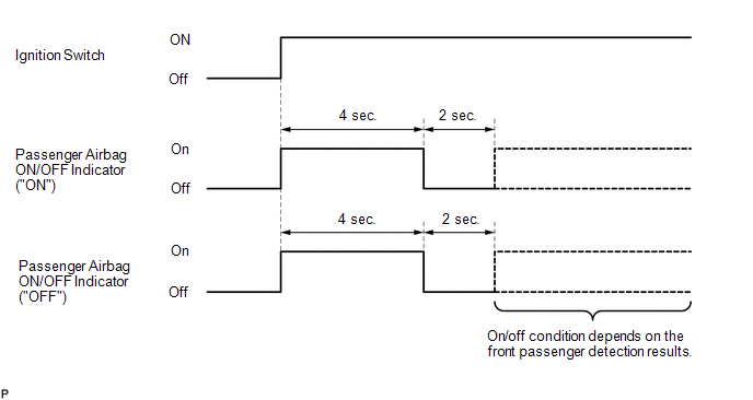
(a) Initial check
(1) Turn the ignition switch to ON.
(2) The passenger airbag ON/OFF indicator comes on for approximately 4 seconds, and then goes off for approximately 2 seconds.
(3) Approximately 6 seconds after the ignition switch is turned to ON, the passenger airbag ON/OFF indicator will be on or off depending on the conditions listed below.
|
Condition |
"ON" Indicator |
"OFF" Indicator |
|---|---|---|
|
Vacant |
Off |
Off |
|
Adult is seated |
On |
Off |
|
Child is seated |
Off |
On |
|
Front passenger occupant classification failure |
Off |
On |
HINT:
- The timing chart below shows the operation of the passenger airbag ON/OFF indicator. Use the chart to check the indicator light circuit.
- When the occupant classification system has trouble, both the SRS warning light and the passenger airbag ON/OFF indicator ("OFF") come on. In this case, check the DTCs for "Airbag System" first. Then troubleshoot the occupant classification system if DTC B1650/32 is output, and troubleshoot the passenger airbag ON/OFF indicator if DTC B1660/43 is output.
5. CHECK PASSENGER AIRBAG ON/OFF INDICATOR
(a) Turn the ignition switch to ON.
(b) Check that the passenger airbag ON/OFF indicator ("ON" and "OFF") comes on for approximately 4 seconds, and then goes off for approximately 2 seconds.
HINT:
In order to check the operation of the passenger airbag ON/OFF indicator when approximately 6 seconds have elapsed after turning the ignition switch to ON, refer to the table in the previous step.
6. ACTIVATION PREVENTION MECHANISM
(a) FUNCTION OF ACTIVATION PREVENTION MECHANISM
(1) An activation prevention mechanism is built into the connector (on the center airbag sensor side) of the airbag system squib circuit to prevent accidental airbag activation.
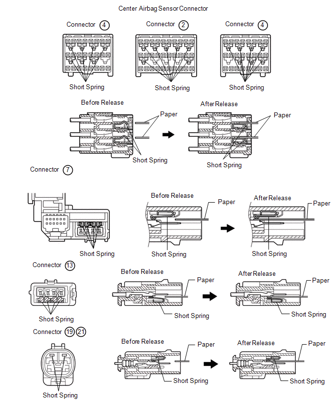
(2) This mechanism closes the circuit when the connector is disconnected by bringing the short spring into contact with the terminals and cutting off external electricity to prevent accidental airbag activation.
(b) RELEASING OF ACTIVATION PREVENTION MECHANISM
(1) To release the activation prevention mechanism, insert a piece of paper with the same thickness as the male terminal (approximately 0.5 mm [0.020 in.]) between the terminals and the short spring to break the connection.
(2) Refer to the following illustrations concerning connectors utilizing the activation prevention mechanism and its release method.
CAUTION:
Never release the activation prevention mechanism on the squib connector even when inspecting with the squib disconnected.
NOTICE:
- Do not release the activation prevention mechanism unless specially directed by the troubleshooting procedure.
- To prevent the terminal and the short spring from being damaged, always use a piece of paper with the same thickness as the male terminal.
.png)
.png)
.png)
.png)
 Terminals Of Ecu
TERMINALS OF ECU
1. AIRBAG SENSOR ASSEMBLY
Terminal No.
Symbol
Destination
F33-1
P2+
Instrument panel passenger airbag assem ...
 Dtc Check / Clear
DTC CHECK / CLEAR
1. CHECK DTC (Using SST Check Wire)
(a) Check for DTCs (present trouble code).
(1) Turn the ignition switch to ON and wait for approximately 60 seconds.
(2) Using SST, connect te ...
Other materials about Toyota 4Runner:
Using the audio control function
Changing sound quality modes
Type A
Pressing selects the mode to be
changed in the following order:
“BAS”→“TRE”→“FAD”→“BAL”→“ASL”
Type B and C Press
.
Press
,
,
,
or
(type C only) as corresponds to
the desired mod ...
Air Inlet Damper Control Servo Motor Circuit (B1442)
DESCRIPTION
The recirculation damper servo sub-assembly sends pulse signals to inform the
No. 1 air conditioning amplifier assembly of the damper position. The No. 1 air
conditioning amplifier assembly activates the motor (normal or reverse) based on
th ...
0.0283