Toyota 4Runner: Front Clearance Sonar Sensor RH Circuit
DESCRIPTION
The ultrasonic sensor sends and receives ultrasonic waves. Based on the received wave, the sensor calculates the approximate distance between the vehicle and the obstacle, and sends the distance value as a signal to the clearance warning ECU assembly.
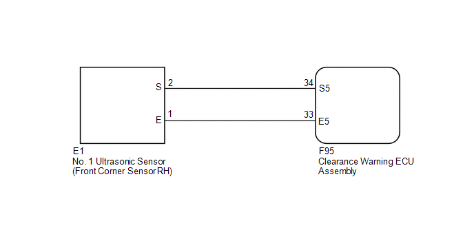
WIRING DIAGRAM
PROCEDURE
|
1. |
REPLACE NO. 1 ULTRASONIC SENSOR (FRONT CORNER SENSOR RH) |
(a) Remove the No. 1 ultrasonic sensor (front corner sensor RH) (See page
.gif) ).
).
(b) Inspect the No. 1 ultrasonic sensor (front corner sensor RH) (See page
).
| NG | .gif) |
REPLACE NO. 1 ULTRASONIC SENSOR (FRONT CORNER SENSOR RH) |
|
.gif)
|
2. |
CHECK HARNESS AND CONNECTOR (FRONT CORNER SENSOR RH - CLEARANCE WARNING ECU ASSEMBLY) |
(a) Disconnect the E1 No. 1 ultrasonic sensor (front corner sensor RH) connector.
(b) Disconnect the F95 clearance warning ECU assembly connector.
(c) Measure the resistance according to the value(s) in the table below.
Standard Resistance:
|
Tester Connection |
Condition |
Specified Condition |
|---|---|---|
|
E1-1 (E) - F95-33 (E5) |
Always |
Below 1 Ω |
|
E1-2 (S) - F95-34 (S5) |
Always |
Below 1 Ω |
|
E1-1 (E) - Body ground |
Always |
10 kΩ or higher |
|
E1-2 (S) - Body ground |
Always |
10 kΩ or higher |
| OK | |
PROCEED TO NEXT SUSPECTED AREA SHOWN IN PROBLEM SYMPTOMS TABLE |
| NG | |
REPAIR OR REPLACE HARNESS OR CONNECTOR |
 Front Clearance Sonar Sensor LH Circuit
DESCRIPTION
The ultrasonic sensor sends and receives ultrasonic waves. Based on the received
wave, the sensor calculates the approximate distance between the vehicle and the
obstacle, and sends t ...
 Rear Clearance Sonar Sensor LH Circuit
DESCRIPTION
The ultrasonic sensor sends and receives ultrasonic waves. Based on the received
wave, the sensor calculates the approximate distance between the vehicle and the
obstacle, and sends t ...
Other materials about Toyota 4Runner:
Diagnosis System
DIAGNOSIS SYSTEM
1. DIAGNOSIS
(a) If the skid control ECU detects a malfunction, the ABS and/or BRAKE warning
lights and the slip indicator lights come on in accordance with the trouble area
to warn the driver.
HINT:
The DTCs are simultaneously ...
Front Passenger Side Solar Sensor Short Circuit (B14A3)
DESCRIPTION
The automatic light control sensor (solar sensor), which is installed on the
upper side of the instrument panel, detects sunlight and controls the air conditioning
in auto mode. The output current from the solar sensor varies according to th ...
0.0087