Toyota 4Runner: Rear Clearance Sonar Sensor LH Circuit
DESCRIPTION
The ultrasonic sensor sends and receives ultrasonic waves. Based on the received wave, the sensor calculates the approximate distance between the vehicle and the obstacle, and sends the distance value as a signal to the clearance warning ECU assembly.
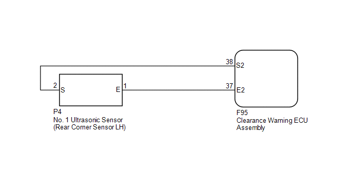
WIRING DIAGRAM
PROCEDURE
|
1. |
INSPECT NO. 1 ULTRASONIC SENSOR (REAR CORNER SENSOR LH) |
(a) Remove the No. 1 ultrasonic sensor (rear corner sensor LH) (See page
.gif) ).
).
(b) Inspect the No. 1 ultrasonic sensor (rear corner sensor LH) (See page
).
| NG | .gif) |
REPLACE NO. 1 ULTRASONIC SENSOR (REAR CORNER SENSOR LH) |
|
.gif)
|
2. |
CHECK HARNESS AND CONNECTOR (REAR CORNER SENSOR LH - CLEARANCE WARNING ECU ASSEMBLY) |
(a) Disconnect the P4 No. 1 ultrasonic sensor (rear corner sensor LH) connector.
(b) Disconnect the F95 clearance warning ECU assembly connector.
(c) Measure the resistance according to the value(s) in the table below.
Standard Resistance:
|
Tester Connection |
Condition |
Specified Condition |
|---|---|---|
|
P4-1 (E) - F95-37 (E2) |
Always |
Below 1 Ω |
|
P4-2 (S) - F95-38 (S2) |
Always |
Below 1 Ω |
|
P4-1 (E) - Body ground |
Always |
10 kΩ or higher |
|
P4-2 (S) - Body ground |
Always |
10 kΩ or higher |
| OK | |
PROCEED TO NEXT SUSPECTED AREA SHOWN IN PROBLEM SYMPTOMS TABLE |
| NG | |
REPAIR OR REPLACE HARNESS OR CONNECTOR |
 Front Clearance Sonar Sensor RH Circuit
DESCRIPTION
The ultrasonic sensor sends and receives ultrasonic waves. Based on the received
wave, the sensor calculates the approximate distance between the vehicle and the
obstacle, and sends t ...
 Rear Clearance Sonar Sensor RH Circuit
DESCRIPTION
The ultrasonic sensor sends and receives ultrasonic waves. Based on the received
wave, the sensor calculates the approximate distance between the vehicle and the
obstacle, and sends t ...
Other materials about Toyota 4Runner:
Installation
INSTALLATION
PROCEDURE
1. INSTALL BRAKE PEDAL SUPPORT ASSEMBLY
(a) Temporarily install the set bolt.
(b) Install the hydraulic brake booster (See page
).
(c) tighten the brake pedal support sub-assembly with the 4 nuts.
Torque:
14 N·m {145 kgf·cm, ...
Accessory meter
The accessory meter presents the driver with a variety of drivingrelated
data including the current outside air temperature.
1. “MODE/ ” button
2. “SET/ ” button
3. Trip information Displays driving range and average fuel consumption
4. Outs ...
0.0103