Toyota 4Runner: System Diagram
SYSTEM DIAGRAM
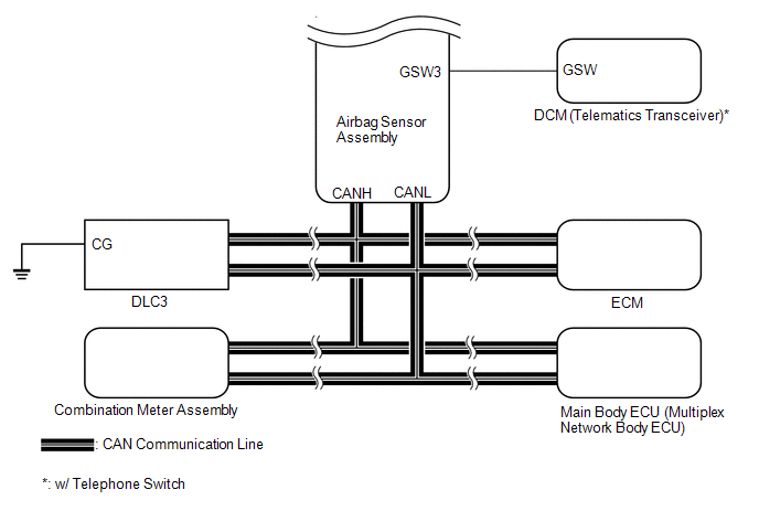
|
Transmitting ECU (Transmitter) |
Receiving ECU |
Signal |
Communication Method |
|---|---|---|---|
|
Center Airbag Sensor |
ECM |
|
CAN |
|
Center Airbag Sensor |
Main Body ECU |
Driver seat buckle switch signal |
|
|
Center Airbag Sensor |
Combination Meter |
|
|
|
Combination Meter |
Center Airbag Sensor |
|
|
|
ECM |
Center Airbag Sensor |
|
 Parts Location
PARTS LOCATION
ILLUSTRATION
ILLUSTRATION
ILLUSTRATION
ILLUSTRATION
...
 How To Proceed With Troubleshooting
CAUTION / NOTICE / HINT
HINT:
Use these procedures to troubleshoot the airbag system.
*: Use the Techstream.
PROCEDURE
1.
VEHICLE BROUGHT TO WORKSHOP
...
Other materials about Toyota 4Runner:
Engine
General Maintenance
GENERAL MAINTENANCE
CAUTION / NOTICE / HINT
HINT:
Work in a well-lighted area. Turn the front wheels fully to the right or left
before beginning the inspection.
PROCEDURE
1. INSPECT DRIVE BELT
(a) Inspect the drive belt (See page ...
Rear Airbag Sensor RH Circuit Malfunction (B1630/23,B1635/24)
DESCRIPTION
The rear airbag sensor consists of the safing sensor, diagnostic circuit,
lateral deceleration sensor, etc.
If the center airbag sensor receives signals from the lateral deceleration
sensor, it determines whether the SRS should ...
0.0268