Toyota 4Runner: Inspection
INSPECTION
PROCEDURE
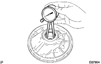
1. INSPECT FRONT OIL PUMP BODY SUB-ASSEMBLY
|
(a) Using a dial indicator, measure the inside diameter of the oil pump body bush. Maximum inside diameter: 38.188 mm (1.50 in.)
|
|
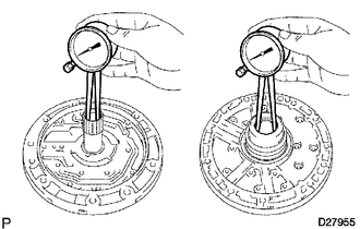
2. INSPECT STATOR SHAFT ASSEMBLY
|
(a) Using a dial indicator, measure the inside diameter of the stator shaft bush. Maximum inside diameter: Front side 21.577 mm (0.849 in.) Rear side 32.08 mm (1.26 in.)
|
|
3. INSPECT CLEARANCE OF OIL PUMP ASSEMBLY
|
(a) Push the driven gear to one side of the body. |
|
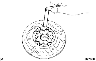
(b) Using a feeler gauge, measure the body clearance.
Standard body clearance:
0.10 to 0.17 mm (0.00394 to 0.00669 in.)
Maximum body clearance:
0.17 mm (0.00669 in.)
- If the body clearance is more than the maximum, replace the drive gear, driven gear or pump body assembly. Replace the part or parts determined to be the most likely cause of the problem.
|
(c) Using a feeler gauge, measure the tip clearance between the driven gear teeth and drive gear teeth. Standard tip clearance: 0.070 to 0.150 mm (0.00276 to 0.00591 in.) Maximum tip clearance: 0.150 mm (0.00591 in.)
|
|

|
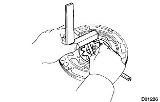
(d) Using a steel straightedge and feeler gauge, measure the side clearance of both gears. Standard side clearance: 0.02 to 0.05 mm (0.000787 to 0.00197 in.) Maximum side clearance: 0.05 mm (0.00197 in.) If the side clearance is more than the maximum, replace the drive gear, driven gear or pump body assembly. Replace the part or parts determined to be the most likely cause of the problem. HINT: There are 5 different drive and driven gear thicknesses. Drive and Driven Gear Thickness:
|
|
4. INSPECT FRONT OIL PUMP DRIVE GEAR ROTATION
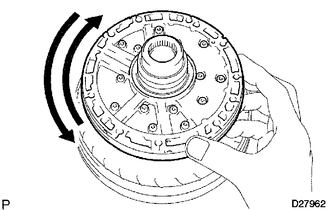
(a) Place the oil pump body on the torque converter clutch.
(b) Check that the drive gear rotates smoothly.
(c) Remove the oil pump assembly from the torque converter clutch.
 Disassembly
DISASSEMBLY
PROCEDURE
1. REMOVE AUTOMATIC TRANSMISSION CASE O-RING
(a) Remove the O-ring from the oil pump assembly.
2. FIX OIL PUMP ASSEMBLY
...
 Reassembly
REASSEMBLY
PROCEDURE
1. INSTALL FRONT OIL PUMP OIL SEAL
(a) Using SST and a hammer, tap in a new oil seal.
SST: 09350-30020
09351-32140
HINT:
Make sure the oil seal end is fl ...
Other materials about Toyota 4Runner:
Alarm
The system sounds the alarm and flashes the lights when forced entry is
detected.
Triggering of the alarm
The alarm is triggered in the following situations when the alarm is set:
• A locked door is unlocked or opened in any way other than using the ...
Reassembly
REASSEMBLY
PROCEDURE
1. INSTALL MAGNET CLUTCH ASSEMBLY
(a) Align the parts as shown in the illustration and install the magnet clutch
stator.
(b) Using a snap ring expander, install a new snap ring with the chamfered
side facing up.
...
0.0279