Toyota 4Runner: Inspection
INSPECTION
PROCEDURE
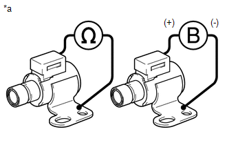
1. INSPECT SHIFT SOLENOID VALVE SR
.png)
(a) Measure the resistance according to the value(s) in the table below.
Standard Resistance:
|
Tester Connection |
Condition |
Specified Condition |
|---|---|---|
|
Shift solenoid valve SR connector terminal - Shift solenoid valve SR body |
20°C (68°F) |
11 to 15 Ω |
|
*a |
Component without harness connected (Shift Solenoid Valve SR) |
(b) Apply 12 V battery voltage to the shift solenoid valve and check that the valve moves and makes an operating noise.
OK:
|
Measurement Condition |
Specified Condition |
|---|---|
|
Valve moves and makes an operating noise |
If the result is not as specified, replace the solenoid valve.
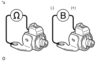
2. INSPECT SHIFT SOLENOID VALVE SL1 AND SL2
.png)
(a) Measure the resistance according to the value(s) in the table below.
Standard Resistance:
|
Tester Connection |
Condition |
Specified Condition |
|---|---|---|
|
1 - 2 |
20°C (68°F) |
5.0 to 5.6 Ω |
|
*a |
Component without harness connected (Shift Solenoid Valve) |
(b) Apply 12 V battery voltage to the shift solenoid valve and check that the valve moves and makes an operating noise.
OK:
|
Measurement Condition |
Specified Condition |
|---|---|
|
Valve moves and makes an operating noise |
If the result is not as specified, replace the solenoid valve.
3. INSPECT SHIFT SOLENOID VALVE SLT AND SLU
.png)
(a) Measure the resistance according to the value(s) in the table below.
Standard Resistance:
|
Tester Connection |
Condition |
Specified Condition |
|---|---|---|
|
1 -2 |
20°C (68°F) |
5.0 to 5.6 Ω |
|
*a |
Component without harness connected (Shift Solenoid Valve) |
(b) Apply 12 V battery voltage to the shift solenoid valve and check that the valve moves and makes an operating noise.
OK:
|
Measurement Condition |
Specified Condition |
|---|---|
|
Battery positive (+) with a 21 W bulb → Terminal 2 Battery negative (-) → Terminal 1 |
Valve moves and makes an operating noise |
If the result is not as specified, replace the solenoid valve.
4. INSPECT SHIFT SOLENOID VALVE S1
(a) Measure the resistance according to the value(s) in the table below.
Standard Resistance:
|
Tester Connection |
Condition |
Specified Condition |
|---|---|---|
|
Shift solenoid valve S1 connector terminal - Shift solenoid valve S1 body |
20°C (68°F) |
11 to 15 Ω |
|
*a |
Component without harness connected (Shift Solenoid Valve S1) |
(b) Apply 12 V battery voltage to the shift solenoid valve and check that the valve moves and makes an operating noise.
OK:
|
Measurement Condition |
Specified Condition |
|---|---|
|
Valve moves and makes an operating noise |
If the result is not as specified, replace the solenoid valve.
5. INSPECT SHIFT SOLENOID VALVE S2
(a) Measure the resistance according to the value(s) in the table below.
Standard Resistance:
|
Tester Connection |
Condition |
Specified Condition |
|---|---|---|
|
Shift solenoid valve S2 connector terminal - Shift solenoid valve S2 body |
20°C (68°F) |
11 to 15 Ω |
|
*a |
Component without harness connected (Shift Solenoid Valve S2) |
(b) Apply 12 V battery voltage to the shift solenoid valve and check that the valve moves and makes an operating noise.
OK:
|
Measurement Condition |
Specified Condition |
|---|---|
|
Valve moves and makes an operating noise |
If the result is not as specified, replace the solenoid valve.
 Disassembly
DISASSEMBLY
PROCEDURE
1. REMOVE SHIFT SOLENOID VALVE SR
(a) Remove the 2 bolts and solenoid valve.
2. REMOVE SHIFT SOLENOID VALVE SLU
...
 Installation
INSTALLATION
PROCEDURE
1. INSTALL TRANSMISSION VALVE BODY ASSEMBLY
(a) Install the spring and check ball body.
(b) Insert the pin of the manual valve into the hole of the manual valve
...
Other materials about Toyota 4Runner:
Disassembly
DISASSEMBLY
PROCEDURE
1. REMOVE BLOWER ASSEMBLY
(a) Remove the bolt.
(b) Detach the 2 claws and remove the blower unit assembly.
2. REMOVE DEFROSTER NOZZLE ASSEMBLY
(a) Detach the 6 claws an ...
Door Courtesy Switch Circuit
DESCRIPTION
The side auto step controller ECU assembly receives the door open/closed signal
from each door courtesy light switch via the side auto step switch assembly.
WIRING DIAGRAM
CAUTION / NOTICE / HINT
HINT:
Inspection should be performed on the ...
0.0117