Toyota 4Runner: Disassembly
DISASSEMBLY
PROCEDURE
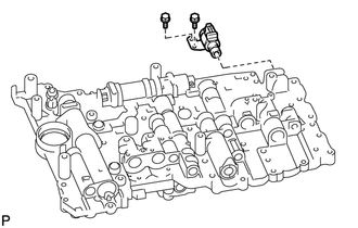
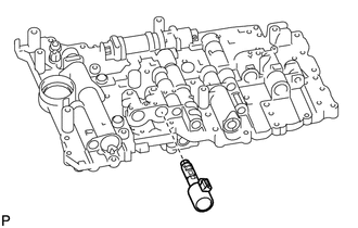
1. REMOVE SHIFT SOLENOID VALVE SR
|
(a) Remove the 2 bolts and solenoid valve. |
|
2. REMOVE SHIFT SOLENOID VALVE SLU
|
(a) Remove the bolt, solenoid lock plate and 2 straight pins. |
|
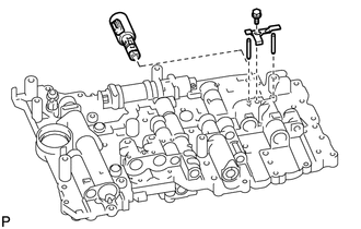
(b) Remove the solenoid valve.
3. REMOVE SHIFT SOLENOID VALVE SL2
4. REMOVE SHIFT SOLENOID VALVE SLT
|
(a) Remove the bolt, solenoid lock plate and 2 straight pins. |
|
(b) Remove the solenoid valve.
5. REMOVE SHIFT SOLENOID VALVE SL1
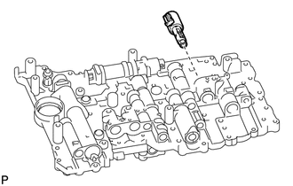
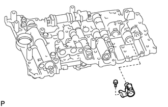
6. REMOVE SHIFT SOLENOID VALVE S1
|
(a) Remove the bolt and shift solenoid valve. |
|
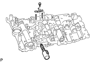
7. REMOVE SHIFT SOLENOID VALVE S2
|
(a) Remove the bolt and solenoid valve. |
|
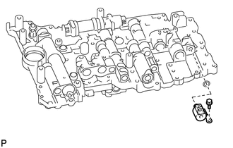
(b) Remove the O-ring from the shift solenoid valve.
 Removal
REMOVAL
PROCEDURE
1. DRAIN AUTOMATIC TRANSMISSION FLUID
2. REMOVE AUTOMATIC TRANSMISSION OIL PAN SUB-ASSEMBLY
3. REMOVE VALVE BODY OIL STRAINER ASSEMBLY
4. DISCONNECT TRANSMISSION WIRE
...
 Inspection
INSPECTION
PROCEDURE
1. INSPECT SHIFT SOLENOID VALVE SR
(a) Measure the resistance according to the value(s) in the table below.
Standard Resistance:
Tester Connection
Co ...
Other materials about Toyota 4Runner:
Power Supply Voltage Malfunction (C1882/82)
DESCRIPTION
The stabilizer control ECU recognizes the ignition switch ON signal based on
the voltage input to the IG terminal.
DTC Code
DTC Detection Condition
Trouble Area
C1882/82
The IG termin ...
Removal
REMOVAL
PROCEDURE
1. REMOVE GENERATOR ASSEMBLY
(a) Remove the generator assembly (See page
).
2. RECOVER REFRIGERANT FROM REFRIGERATION SYSTEM
3. DISCONNECT DISCHARGE HOSE SUB-ASSEMBLY
(a) Remove the bolt and disconnect the discharge hos ...
0.0069