Toyota 4Runner: Inspection
INSPECTION
PROCEDURE
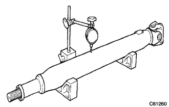
1. INSPECT PROPELLER SHAFT ASSEMBLY
|
(a) Using a dial indicator, check the propeller shaft runout. Maximum runout: 0.4 mm (0.0157 in.) If the shaft runout is more than the maximum, replace the shaft. |
|
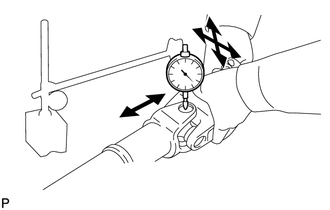
2. INSPECT REAR PROPELLER SHAFT UNIVERSAL JOINT SPIDER BEARING
NOTICE:
Be careful not to grip the propeller shaft tube too tightly in a vise as this will cause deformation.
(a) Check the spider bearings for wear or damage.
If necessary, replace the spider bearing.
|
(b) Check the spider bearing axial play by turning the yoke while holding the shaft tightly. Maximum bearing axial play: 0 mm (0 in.) If the axial play is more than the maximum, replace the spider bearing. |
|
 Removal
REMOVAL
PROCEDURE
1. REMOVE PROPELLER SHAFT ASSEMBLY
(a) Place matchmarks on the propeller shaft flange and differential flange.
Text in Illustration
*a
...
 Reassembly
REASSEMBLY
PROCEDURE
1. INSTALL REAR PROPELLER SHAFT UNIVERSAL JOINT SPIDER BEARING
HINT:
Use the same procedure for all rear propeller shaft universal joint spider bearing.
(a) Apply ...
Other materials about Toyota 4Runner:
Inspection
INSPECTION
PROCEDURE
1. CHECK BRAKE CYLINDER AND PISTON
(a) Check the cylinder bore and piston for rust or scoring.
If necessary, replace the disc brake cylinder assembly.
2. CHECK PAD LINING THICKNESS
(a) Using a ruler, measure the pad lining ...
Reassembly
REASSEMBLY
CAUTION / NOTICE / HINT
PROCEDURE
1. INSTALL PLUG
(a) Using the SST and a hammer, install a new plug.
SST: 09950-60010
09951-00450
SST: 09950-70010
09951-07100
2. INSTALL FRO ...
0.0282