Toyota 4Runner: Removal
REMOVAL
PROCEDURE
1. REMOVE PROPELLER SHAFT ASSEMBLY
|
(a) Place matchmarks on the propeller shaft flange and differential flange. Text in Illustration
|
|
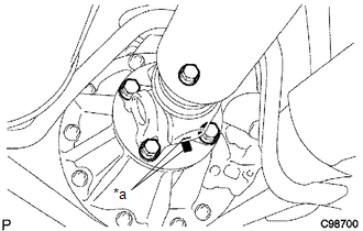
(b) Remove the 4 nuts, 4 bolts and 4 washers.
|
(c) Remove the propeller shaft. |
|
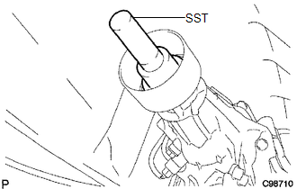
(d) Insert SST into the transmission to prevent oil leakage.
SST: 09325-40010
 Disassembly
DISASSEMBLY
PROCEDURE
1. REMOVE REAR PROPELLER SHAFT UNIVERSAL JOINT SPIDER BEARING
HINT:
Use the same procedure for all rear propeller shaft universal joint spider bearing.
(a) Place ...
 Inspection
INSPECTION
PROCEDURE
1. INSPECT PROPELLER SHAFT ASSEMBLY
(a) Using a dial indicator, check the propeller shaft runout.
Maximum runout:
0.4 mm (0.0157 in.)
If the shaft runout i ...
Other materials about Toyota 4Runner:
Air Conditioning Compressor Magnetic Clutch Circuit
DESCRIPTION
When the air conditioning amplifier assembly is turned on, a magnet clutch assembly
signal is sent from the MGC terminal of the air conditioning amplifier assembly.
Then, the A/C COMP relay turns on to operate the magnet clutch assembly.
WIRI ...
Sleep Operation Failure of Occupant Classification ECU (B1796)
DESCRIPTION
During sleep mode, the occupant classification ECU monitors the condition of
each sensor while the ignition switch is off. In this mode, if the occupant classification
ECU detects an internal malfunction, DTC B1796 is stored.
DTC C ...
0.0086