Toyota 4Runner: Installation
INSTALLATION
PROCEDURE
1. ADJUST COMPRESSOR OIL
(a) When replacing the compressor and magnetic clutch with a new one, gradually discharge the refrigerant gas from the service valve and drain the following amount of oil from the new compressor and magnetic clutch before installation.
Standard:
(Oil capacity inside the new compressor and magnetic clutch: 120 + 15 cc (4.1 + 0.51 fl.oz.)) - (Remaining oil amount in the removed compressor and magnetic clutch) = (Oil amount to be removed from the new compressor when replacing)
NOTICE:
- When checking the compressor oil level, follow the A/C system precautions.
- If a new compressor and magnetic clutch is installed without removing some of the oil remaining in the pipes of the vehicle, the oil amount will be too large. This prevents heat exchange in the refrigerant cycle and causes refrigerant failure.
- If the volume of oil remaining in the removed compressor and magnetic clutch is too small, check for oil leakage.
- Be sure to use ND-OIL 8 or equivalent compressor oil.
2. INSTALL COOLER COMPRESSOR ASSEMBLY

(a) Install the cooler compressor with the stud bolt.
Torque:
10 N·m {102 kgf·cm, 7 ft·lbf}
(b) Install the 3 bolts and nut.
Torque:
25 N·m {255 kgf·cm, 18 ft·lbf}
HINT:
Tighten the bolts and nut in the order shown in the illustration.
(c) Connect the connector.
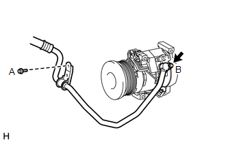
3. CONNECT SUCTION HOSE SUB-ASSEMBLY
(a) Remove the attached vinyl tape from the suction hose.
(b) Sufficiently apply compressor oil to a new O-ring and the fitting surface of the cooler compressor.
Compressor oil:
ND-OIL 8 or equivalent
(c) Install the O-ring to the suction hose.
|
(d) Connect the suction hose with the 2 bolts. Torque: for bolt A : 7.8 N·m {80 kgf·cm, 69 in·lbf} for bolt B : 9.8 N·m {100 kgf·cm, 87 in·lbf} |
|
4. CONNECT DISCHARGE HOSE SUB-ASSEMBLY
(a) Remove the attached vinyl tape from the cooler refrigerant discharge hose.
(b) Sufficiently apply compressor oil to a new O-ring and the fitting surface of the cooler compressor.
Compressor oil:
ND-OIL 8 or equivalent
(c) Install the O-ring to the discharge hose.
(d) Connect the discharge hose to the cooler compressor with the bolt.
Torque:
9.8 N·m {100 kgf·cm, 87 in·lbf}
5. INSTALL GENERATOR ASSEMBLY
(a) Install the generator assembly (See page .gif)
).
6. CHARGE REFRIGERANT
7. WARM UP ENGINE
8. CHECK FOR REFRIGERANT GAS LEAK
 Removal
REMOVAL
PROCEDURE
1. REMOVE GENERATOR ASSEMBLY
(a) Remove the generator assembly (See page
).
2. RECOVER REFRIGERANT FROM REFRIGERATION SYSTEM
3. DISCONNECT DISCHARGE HOSE SUB-ASSEMBLY
...
 Reassembly
REASSEMBLY
PROCEDURE
1. INSTALL MAGNET CLUTCH ASSEMBLY
(a) Align the parts as shown in the illustration and install the magnet clutch
stator.
(b) Using a snap ring expander, install ...
Other materials about Toyota 4Runner:
Brake Warning Light Remains ON
DESCRIPTION
The BRAKE warning light comes on when brake fluid is insufficient, the parking
brake is applied or the EBD is defective.
WIRING DIAGRAM
CAUTION / NOTICE / HINT
NOTICE:
When replacing the master cylinder solenoid, perform calibration (See p ...
Inspection
INSPECTION
PROCEDURE
1. INSPECT FRONT SHOCK ABSORBER ASSEMBLY LH
(a) Compress and extend the shock absorber rod and check that there is no abnormal
resistance or unusual sound during operation.
If there is any abnormality, replace the front shock absorbe ...
0.0184