Toyota 4Runner: Removal
REMOVAL
PROCEDURE
1. REMOVE GENERATOR ASSEMBLY
(a) Remove the generator assembly (See page .gif)
).
2. RECOVER REFRIGERANT FROM REFRIGERATION SYSTEM
3. DISCONNECT DISCHARGE HOSE SUB-ASSEMBLY
|
(a) Remove the bolt and disconnect the discharge hose from the cooler compressor. |
|
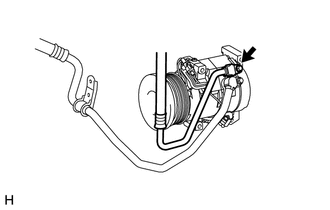
(b) Remove the O-ring from the discharge hose.
NOTICE:
Seal the openings of the disconnected parts using vinyl tape to prevent moisture and foreign matter from entering them.
4. DISCONNECT SUCTION HOSE SUB-ASSEMBLY
|
(a) Remove the 2 bolts and disconnect the suction hose from the cooler compressor. |
|
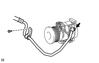
(b) Remove the O-ring from the suction hose.
NOTICE:
Seal the openings of the disconnected parts using vinyl tape to prevent moisture and foreign matter from entering them.
5. REMOVE COOLER COMPRESSOR ASSEMBLY
|
(a) Disconnect the connector. |
|
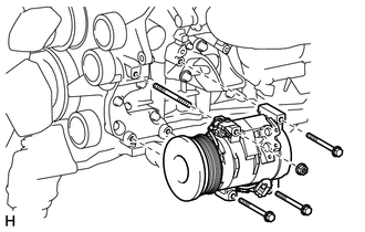
(b) Remove the 3 bolts and nut.
(c) Remove the stud bolt and cooler compressor.
 Inspection
INSPECTION
PROCEDURE
1. INSPECT MAGNET CLUTCH ASSEMBLY
(a) Check the magnet clutch operation.
(1) Confirm that the magnet clutch hub and magnet clutch rotor lock when the
positive (+) lead of ...
 Installation
INSTALLATION
PROCEDURE
1. ADJUST COMPRESSOR OIL
(a) When replacing the compressor and magnetic clutch with a new one, gradually
discharge the refrigerant gas from the service valve and drain the ...
Other materials about Toyota 4Runner:
Rear Door Speaker
Components
COMPONENTS
ILLUSTRATION
Removal
REMOVAL
CAUTION / NOTICE / HINT
HINT:
Use the same procedure for the RH and LH sides.
The procedure listed below is for the LH side.
PROCEDURE
1. REMOVE REAR DOOR INSIDE HANDLE BEZEL L ...
ECU Circuit (61)
DESCRIPTION
When the internal circuit of the side auto step controller ECU assembly malfunctions,
the side auto step controller ECU assembly halts the operation of the system.
DTC No.
DTC Detection Condition
Trouble Area
...
0.0271