Toyota 4Runner: Installation
INSTALLATION
CAUTION / NOTICE / HINT
HINT:
A bolt without a torque specification is shown in the standard bolt chart (See
page .gif) ).
).
PROCEDURE
1. INSTALL REAR CONSOLE BOX ASSEMBLY
(a) Connect each connector.
(b) Attach the 2 guides.
(c) Install the rear console box assembly with the 4 bolts and 2 screws.
2. INSTALL NO. 2 CONSOLE BOX RETAINER
(a) Attach the clip, 2 claws and 2 guides to install the No. 2 console box retainer.
3. INSTALL UPPER CONSOLE PANEL SUB-ASSEMBLY
(a) Connect each connector.
(b) Attach the 10 clips to install the upper console panel sub-assembly.
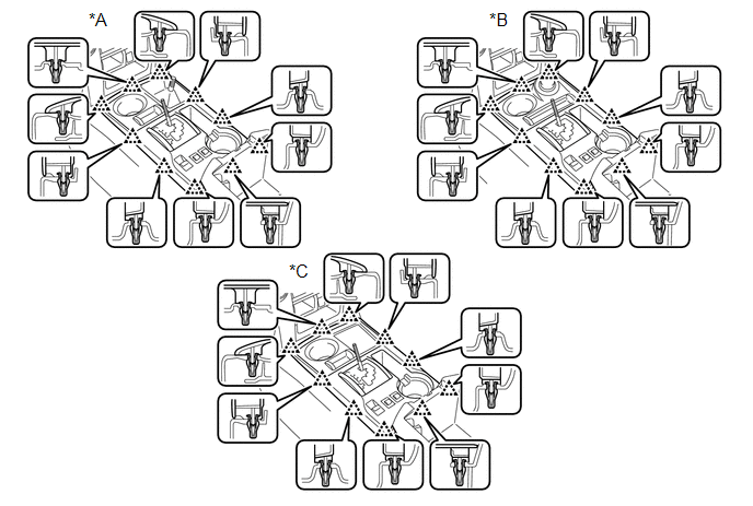 Text in Illustration
|
*A |
for VF2A |
*B |
for VF2BM, VF4BM |
|
*C |
for 2WD |
- |
- |
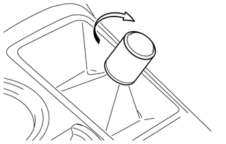
4. INSTALL SHIFT LEVER KNOB SUB-ASSEMBLY (for VF2A)
|
(a) Install the shift lever knob sub-assembly and turn it in the direction indicated by the arrow. |
|
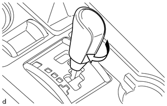
5. INSTALL SHIFT LEVER KNOB SUB-ASSEMBLY
|
(a) Install the shift lever knob sub-assembly and turn it in the direction indicated by the arrow. |
|
6. INSTALL FRONT NO. 1 CONSOLE BOX INSERT
(a) Attach the 2 clips and 2 guides to install the front No. 1 console box insert.
7. INSTALL FRONT NO. 2 CONSOLE BOX INSERT
(a) Attach the 2 clips and guide to install the front No. 2 console box insert.
8. INSTALL NO. 1 INSTRUMENT CLUSTER FINISH PANEL GARNISH
(a) Attach the 5 clips to install the No. 1 instrument cluster finish panel garnish.
9. INSTALL NO. 2 INSTRUMENT CLUSTER FINISH PANEL GARNISH
 Removal
REMOVAL
PROCEDURE
1. REMOVE NO. 1 INSTRUMENT CLUSTER FINISH PANEL GARNISH
(a) Put protective tape around the No. 1 instrument cluster finish panel garnish.
(b) Grip the No. 1 instrument cluster fi ...
 Reassembly
REASSEMBLY
PROCEDURE
1. INSTALL TRANSFER POSITION SWITCH (for VF2BM)
2. INSTALL TRANSFER POSITION SWITCH (for VF4BM)
3. INSTALL NO. 2 BOX BOTTOM MAT (for 2WD)
(a) Attach the 4 claws to inst ...
Other materials about Toyota 4Runner:
Speaker Output Short (B15C3)
DESCRIPTION
This DTC is stored when a malfunction occurs in the speakers.
DTC No.
DTC Detection Condition
Trouble Area
B15C3
A short is detected in the speaker output circuit.
...
Operation Check
OPERATION CHECK
1. CHECK INITIAL CHECK FUNCTION
(a) Check the initial check function for the buzzer.
(1) When the back sonar or clearance sonar switch assembly is turned on, check
that the following occurs: 1) after 0.2 seconds, the buzzer sounds for ap ...
0.0174