Toyota 4Runner: Lost Communication with Combination Meter (B2661,B2662)
DESCRIPTION
This DTC is stored when LIN communication between the drive monitor switch and combination meter assembly stops 10 seconds or more.
|
DTC Code |
DTC Detection Condition |
Trouble Area |
|---|---|---|
|
B2661 |
No communication between the drive monitor switch and combination meter assembly for 10 seconds or more. |
|
|
B2662 |
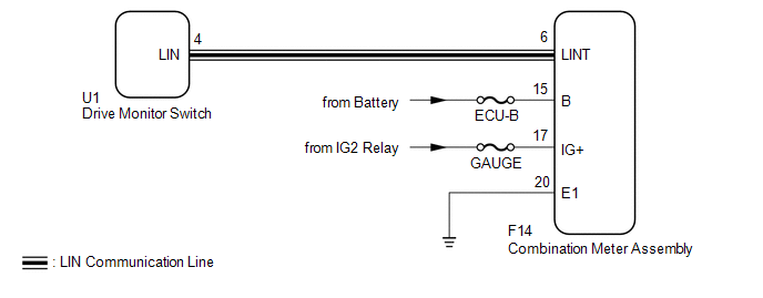
WIRING DIAGRAM
CAUTION / NOTICE / HINT
NOTICE:
- When using the Techstream with the ignition switch off to troubleshoot:
Connect the Techstream to the vehicle and turn a courtesy light switch on and off at 1.5 second intervals until communication between the Techstream and vehicle begins.
- Inspect the fuses and bulbs for circuits related to this system before performing the following inspection procedure.
HINT:
As the combination meter assembly incorporates the accessory meter function, DTC B2662 is stored at the same time as B2661. The accessory meter assembly does not support LIN communication. Therefore, if DTCs B2661 and B2662 are stored, check for communication disruptions between the drive monitor switch and the combination meter assembly.
PROCEDURE
|
1. |
CLEAR DTC |
(a) Clear the DTCs (See page .gif) ).
).
|
.gif)
|
2. |
CHECK FOR DTC |
(a) Check for DTCs (See page ).
OK:
DTC B2661 and B2662 are not output.
| OK | .gif) |
USE SIMULATION METHOD TO CHECK |
|
|
3. |
CHECK HARNESS AND CONNECTOR (DRIVE MONITOR SWITCH - COMBINATION METER ASSEMBLY) |
(a) Disconnect the U1 drive monitor switch connector.
(b) Disconnect the F14 combination meter assembly connector.
(c) Measure the resistance according to the value(s) in the table below.
Standard Resistance:
|
Tester Connection |
Condition |
Specified Condition |
|---|---|---|
|
U1-4 (LIN) - F14-6 (LINT) |
Always |
Below 1 Ω |
|
U1-4 (LIN) or F14-6 (LINT) - Body ground |
Always |
10 kΩ or higher |
| NG | |
REPAIR OR REPLACE HARNESS OR CONNECTOR |
|
|
4. |
CHECK HARNESS AND CONNECTOR (COMBINATION METER ASSEMBLY - BATTERY AND BODY GROUND) |
|
(a) Disconnect the F14 combination meter assembly connector. |
|
(b) Measure the resistance according to the value(s) in the table below.
Standard Resistance:
|
Tester Connection |
Condition |
Specified Condition |
|---|---|---|
|
F14-20 (E1) - Body ground |
Always |
Below 1 Ω |
(c) Measure the voltage according to the value(s) in the table below.
Standard Voltage:
|
Tester Connection |
Switch Condition |
Specified Condition |
|---|---|---|
|
F14-15 (B) - Body ground |
Always |
11 to 14 V |
|
F14-17 (IG+) - Body ground |
Ignition switch ON |
11 to 14 V |
|
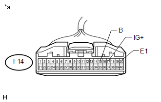
*a |
Front view of wire harness connector (to Combination Meter Assembly) |
| NG | |
REPAIR OR REPLACE HARNESS OR CONNECTOR |
|
|
5. |
REPLACE COMBINATION METER ASSEMBLY |
(a) Temporarily replace the combination meter assembly with a new one (See page
).
|
|
6. |
CLEAR DTC |
(a) Clear the DTCs (See page ).
|
|
7. |
CHECK FOR DTC |
(a) Check for DTCs (See page ).
| OK | |
END (COMBINATION METER ASSEMBLY IS DEFECTIVE) |
| NG | |
REPLACE DRIVE MONITOR SWITCH |
 No Response from ID BOX (B2789)
DESCRIPTION
This DTC is stored when LIN communication between the certification ECU and ID
code box stops for 10 seconds or more.
DTC Code
DTC Detection Condition
...
 Lost Communication with Back Door Power Window ECU (Abnormal Power Supply) (B2327,B2328)
DESCRIPTION
DTC B2327 is stored when LIN communication between the multiplex network
door ECU (back door P/W) and back door power window regulator motor assembly
stops for 10 seconds o ...
Other materials about Toyota 4Runner:
Lost Communication with ECM/PCM "A" (U0100/71,U0122/71,U0124/71,U0126/71)
DESCRIPTION
DTC Code
DTC Detection Condition
Trouble Area
U0100/71
While driving at 30 km/h (19 mph), the ECM indicates a CAN communication
stop for 3 seconds or more.
CAN communicati ...
System Diagram
SYSTEM DIAGRAM
Communication Table
Transmitting ECU
(Transmitter)
Receiving ECU
(Receiver)
Signal
Line
ECM
Power management control ECU
Crankshaft position sensor signa ...
0.0067