Toyota 4Runner: Mayday Battery
Components
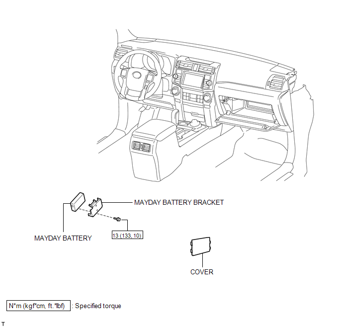
COMPONENTS
ILLUSTRATION
Removal
REMOVAL
PROCEDURE
1. DISCONNECT CABLE FROM NEGATIVE BATTERY TERMINAL
NOTICE:
When disconnecting the cable, some systems need to be initialized after the cable
is reconnected (See page .gif) ).
).
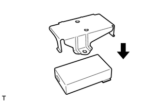
2. REMOVE MAYDAY BATTERY WITH BRACKET
|
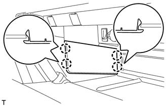
(a) Detach the 4 claws and remove the cover. |
|
|
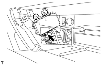
(b) Remove the bolt and detach the 2 claws. |
|
|
(c) Move the mayday battery with bracket as shown in the illustration. |
|
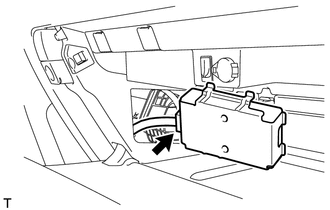
(d) Disconnect the connector and remove the mayday battery with bracket.
3. REMOVE MAYDAY BATTERY
|
(a) Remove the bracket from the mayday battery. |
|

Installation
INSTALLATION
PROCEDURE
1. INSTALL MAYDAY BATTERY
|
(a) Install the bracket to the battery. |
|
2. INSTALL MAYDAY BATTERY WITH BRACKET
|
(a) Connect the connector. |
|
.png)
|
(b) Attach the 2 claws and install the mayday battery with bracket with the bolt. Torque: 13 N·m {133 kgf·cm, 10 ft·lbf} |
|
.png)
|
(c) Attach the 4 claws to install the cover. |
|
.png)
3. CONNECT CABLE TO NEGATIVE BATTERY TERMINAL
NOTICE:
When disconnecting the cable, some systems need to be initialized after the cable
is reconnected (See page .gif) ).
).
4. CHECK SRS WARNING LIGHT
(a) Check the SRS warning light (See page ).
5. PERFORM REGISTRATION
(a) Perform registration (See page ).
NOTICE:
When replacing the mayday battery or DCM (telematics transceiver) together with the mayday battery, perform registration.
 Manual(sos)switch
Components
COMPONENTS
ILLUSTRATION
ILLUSTRATION
Installation
INSTALLATION
PROCEDURE
1. INSTALL TELEPHONE SWITCH ASSEMBLY
(a) Install the telephone switch with the 2 screws.
(b) Connec ...

Other materials about Toyota 4Runner:
Disassembly
DISASSEMBLY
PROCEDURE
1. REMOVE NO. 1 POWER OUTLET SOCKET ASSEMBLY
2. REMOVE NO. 1 POWER OUTLET SOCKET COVER
3. REMOVE REAR CONSOLE END PANEL
(a) Detach the 4 clips and 4 claws to remove the rear console end panel.
...
Steering Pad Switch Circuit
DESCRIPTION
This circuit sends an operation signal from the steering pad switch assembly
to the navigation receiver assembly.
If there is an open in the circuit, the audio system cannot be operated using
the steering pad switch assembly.
If there is a s ...
0.0084