Toyota 4Runner: Manual(sos)switch
Components
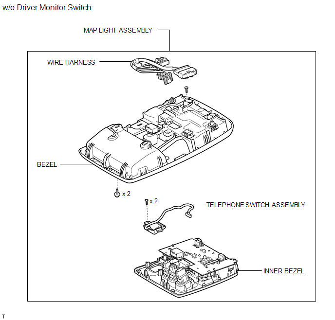
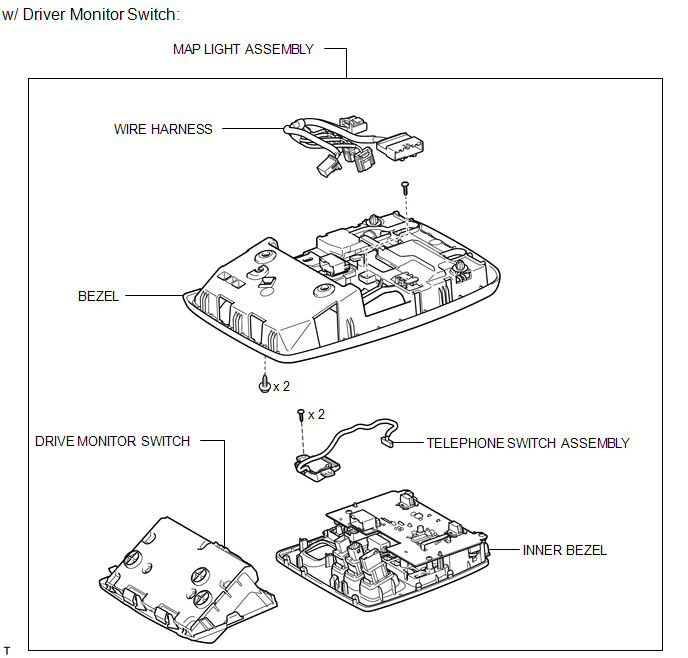
COMPONENTS
ILLUSTRATION
ILLUSTRATION
Installation
INSTALLATION
PROCEDURE
1. INSTALL TELEPHONE SWITCH ASSEMBLY
(a) Install the telephone switch with the 2 screws.
(b) Connect the connector.
(c) Attach the 8 claws to install the inner bezel.
(d) Install the screw.
(e) Connect the 6 connectors.
2. INSTALL MAP LIGHT ASSEMBLY
.gif)
3. INSTALL DRIVE MONITOR SWITCH
Removal
REMOVAL
PROCEDURE
1. REMOVE DRIVE MONITOR SWITCH
.gif)
2. REMOVE MAP LIGHT ASSEMBLY
3. REMOVE TELEPHONE SWITCH ASSEMBLY
|
(a) Disconnect the 6 connectors. |
|
.png)
|
(b) Remove the screw. |
|
.png)
|
(c) Detach the 8 claws and remove the inner bezel. |
|
.png)
|
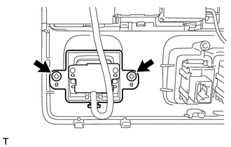
(d) Remove the 2 screws and telephone switch. |
|
 Installation
INSTALLATION
PROCEDURE
1. INSTALL NO. 2 TELEPHONE BRACKET
(a) Install the bracket with the 2 bolts.
2. INSTALL NO. 1 TELEPHONE BRACKET
(a) Install the bracket with the 3 bolts.
(b) Connect the 2 ...
 Mayday Battery
Components
COMPONENTS
ILLUSTRATION
Removal
REMOVAL
PROCEDURE
1. DISCONNECT CABLE FROM NEGATIVE BATTERY TERMINAL
NOTICE:
When disconnecting the cable, some systems need to be initialized ...
Other materials about Toyota 4Runner:
Side Auto Step Switch Circuit
DESCRIPTION
The side auto step controller ECU assembly receives the door open/closed signal
from each door courtesy light switch via the side auto step switch assembly.
WIRING DIAGRAM
CAUTION / NOTICE / HINT
HINT:
Inspection should be performed on the ...
Removal
REMOVAL
CAUTION / NOTICE / HINT
HINT:
Use the same procedure for the RH and LH sides.
The procedure listed below is for the LH side.
When removing the window frame moulding, black out tape and outside
stripe, heat the vehicle body, windo ...
0.022