Toyota 4Runner: Suspension Control ECU Communication Stop Mode
DESCRIPTION
|
Detection Item |
Symptom |
Trouble Area |
|---|---|---|
|
Suspension Control ECU Communication Stop Mode |
Either condition is met:
|
|
HINT:
For vehicles with a kinetic dynamic suspension system only.
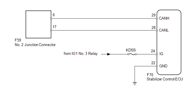
WIRING DIAGRAM
CAUTION / NOTICE / HINT
NOTICE:
Inspect the fuses for circuits related to this system before performing the following inspection procedure.
HINT:
Operating the ignition switch, any switches or any doors triggers related ECU and sensor communication with the CAN, which causes resistance variation.
PROCEDURE
|
1. |
DISCONNECT CABLE FROM NEGATIVE BATTERY TERMINAL |
(a) Disconnect the cable from the negative (-) battery terminal before measuring the resistances of the main wire and branch wire.
CAUTION:
Wait at least 90 seconds after disconnecting the cable from the negative (-) battery terminal to disable the SRS system.
NOTICE:
When disconnecting the cable, some systems need to be initialized after the cable
is reconnected (See page .gif) ).
).
|
.gif)
|
2. |
CHECK FOR OPEN IN CAN BUS WIRE (STABILIZER CONTROL ECU BRANCH WIRE) |
|
(a) Disconnect the F70 stabilizer control ECU connector. |
|
(b) Measure the resistance according to the value(s) in the table below.
Standard Resistance:
|
Tester Connection |
Switch Condition |
Specified Condition |
|---|---|---|
|
F70-29 (CANH) - F70-28 (CANL) |
Ignition switch off |
54 to 69 Ω |
|
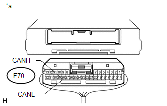
*a |
Rear view of wire harness connector (to Stabilizer Control ECU) |
| NG | .gif) |
REPAIR OR REPLACE STABILIZER CONTROL ECU BRANCH WIRE OR CONNECTOR (CANH, CANL) |
|
|
3. |
CHECK HARNESS AND CONNECTOR (STABILIZER CONTROL ECU - BATTERY AND BODY GROUND) |
|
(a) Connect the cable to the negative (-) battery terminal. NOTICE: When disconnecting the cable, some systems need to be initialized after
the cable is reconnected (See page |
|
(b) Measure the resistance according to the value(s) in the table below.
Standard Resistance:
|
Tester Connection |
Condition |
Specified Condition |
|---|---|---|
|
F70-22 (GND) - Body ground |
Always |
Below 1 Ω |
(c) Measure the voltage according to the value(s) in the table below.
Standard Voltage:
|
Tester Connection |
Switch Condition |
Specified Condition |
|---|---|---|
|
F70-24 (IG) - Body ground |
Ignition switch ON |
11 to 14 V |
|
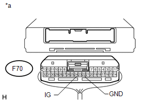
*a |
Rear view of wire harness connector (to Stabilizer Control ECU) |
| OK | |
REPLACE STABILIZER CONTROL ECU |
| NG | |
REPAIR OR REPLACE HARNESS OR CONNECTOR |
 4WD Control ECU Communication Stop Mode
DESCRIPTION
Detection Item
Symptom
Trouble Area
4WD Control ECU Communication Stop Mode
Either condition is met:
"Four ...
 Navigation Receiver Assembly Communication Stop Mode
DESCRIPTION
Detection Item
Symptom
Trouble Area
Navigation Receiver Assembly Communication Stop Mode
Either condition is met:
...
Other materials about Toyota 4Runner:
Reassembly
REASSEMBLY
PROCEDURE
1. INSTALL KEY INTERLOCK SOLENOID WIRE (w/o Smart Key System)
(a) Install the key interlock solenoid wire on to the install the ignition switch.
2. INSTALL IGNITION SWITCH ASSEMBLY (w/o Smart Key System)
(a) Install the ign ...
Window Glass Antenna Wire
On-vehicle Inspection
ON-VEHICLE INSPECTION
PROCEDURE
1. INSPECT WINDOW GLASS ANTENNA WIRE
(a) Check for continuity of the window glass antenna wire.
Text in Illustration
*a
Tester Probe
...

0.0072