Toyota 4Runner: On-vehicle Inspection
ON-VEHICLE INSPECTION
PROCEDURE
1. REMOVE FRONT WHEEL
2. REMOVE DISC BRAKE CYLINDER ASSEMBLY LH
.gif)
3. REMOVE FRONT DISC
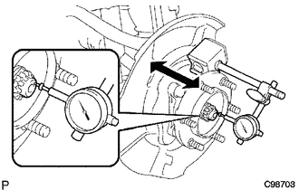
4. INSPECT FRONT AXLE HUB BEARING LOOSENESS
|
(a) Using a dial indicator, measure the looseness near the center of the axle hub. Maximum looseness: 0.05 mm (0.00197 in.) NOTICE: Make sure that the dial indicator is set at a right angle to the measurement surface. If the looseness is more than the maximum, replace the axle hub. |
|
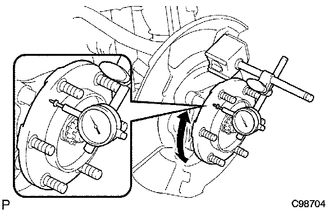
5. INSPECT FRONT AXLE HUB RUNOUT
|
(a) Using a dial indicator, measure the runout on the surface of the axle hub outside the hub bolts. Maximum runout: 0.08 mm (0.00315 in.) NOTICE: Make sure that the dial indicator is set at a right angle to the measurement surface. If the runout is more than the maximum, replace the axle hub. |
|
6. INSTALL FRONT DISC
7. INSTALL DISC BRAKE CYLINDER ASSEMBLY LH
8. INSTALL FRONT WHEEL
Torque:
for aluminum wheel :
103 N·m {1050 kgf·cm, 76 ft·lbf}
for steel wheel :
112 N·m {1142 kgf·cm, 83 ft·lbf}
 Components
COMPONENTS
ILLUSTRATION
...
 Removal
REMOVAL
CAUTION / NOTICE / HINT
HINT:
Use the same procedure for the RH and LH sides.
The procedure listed below is for the LH side.
PROCEDURE
1. REMOVE FRONT WHEEL
2. REMOVE D ...
Other materials about Toyota 4Runner:
Removal
REMOVAL
PROCEDURE
1. DISCONNECT CABLE FROM NEGATIVE BATTERY TERMINAL
NOTICE:
When disconnecting the cable, some systems need to be initialized after the cable
is reconnected (See page ).
2. REMOVE LOWER STEERING COLUMN COVER
(a) Turn the st ...
Id Code Box
Components
COMPONENTS
ILLUSTRATION
Installation
INSTALLATION
PROCEDURE
1. INSTALL ID CODE BOX
(a) Attach the 2 claws and move the ID code box in the direction of the
arrow.
(b) M ...
0.0094