Toyota 4Runner: Id Code Box
Components
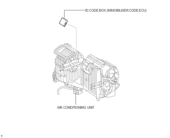
COMPONENTS
ILLUSTRATION
Installation
INSTALLATION
PROCEDURE
1. INSTALL ID CODE BOX
|
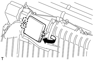
(a) Attach the 2 claws and move the ID code box in the direction of the arrow. |
|
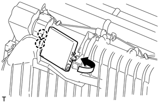
|
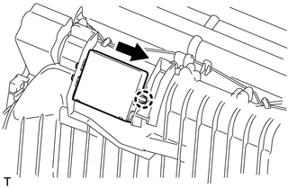
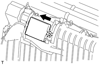
(b) Move the ID code box in the direction of the arrow to attach the claw and install the ID code box. |
|
2. INSTALL INSTRUMENT PANEL REINFORCEMENT ASSEMBLY WITH AIR CONDITIONING UNIT ASSEMBLY
(a) Install the air conditioning unit (See page
.gif) ).
).
3. REGISTER ECU CODE
(a) Register the ECU code (See page ).
Removal
REMOVAL
PROCEDURE
1. REMOVE INSTRUMENT PANEL REINFORCEMENT ASSEMBLY WITH AIR CONDITIONING UNIT ASSEMBLY
(a) Remove the air conditioning unit (See page
.gif) ).
).
2. REMOVE ID CODE BOX
|
(a) Move the ID code box in the direction of the arrow in the illustration to detach the claw. |
|
|
(b) Move the ID code box in the direction of the arrow to detach the 2 claws and remove the ID code box. |
|
 ECU Power Source Circuit
DESCRIPTION
This circuit provides power to operate the transponder key ECU assembly.
WIRING DIAGRAM
CAUTION / NOTICE / HINT
NOTICE:
Inspect the fuses for circuits related to this system before ...
 Security Horn Assembly
Components
COMPONENTS
ILLUSTRATION
Removal
REMOVAL
PROCEDURE
1. REMOVE AIR CLEANER CAP AND HOSE
2. REMOVE AIR CLEANER CASE SUB-ASSEMBLY
3. REMOVE SECURITY HORN ASSEMBLY
...
Other materials about Toyota 4Runner:
Installation
INSTALLATION
PROCEDURE
1. INSTALL FRONT POWER WINDOW REGULATOR MOTOR ASSEMBLY LH
NOTICE:
The regulator arm must be below the intermediate position when installing the
power window regulator motor.
(a) Using a T25 "TORX" socket wrenc ...
Power Source Mode does not Change to ON (ACC)
DESCRIPTION
When the engine switch is pushed with the key in the cabin, the power management
control ECU receives signals to switch the power source mode.
HINT:
To allow use of the Techstream to inspect the push-button start function when
the engine swi ...
0.0143