Toyota 4Runner: Open Circuit in Transfer 4WD Position Switch Circuit (C1258,C1340)
DESCRIPTION
|
DTC Code |
DTC Detection Condition |
Trouble Area |
|---|---|---|
|
C1258*1 C1340*2 |
An open circuit is detected in the EXI circuit of the skid control ECU. |
|
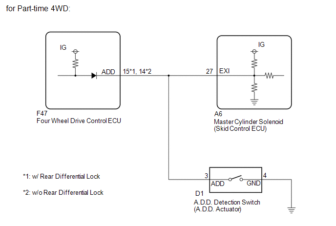
*1: for Part-time 4WD
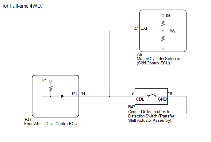
*2: for Full-time 4WD
WIRING DIAGRAM
CAUTION / NOTICE / HINT
NOTICE:
When replacing the master cylinder solenoid, perform calibration (See page
.gif) ).
).
PROCEDURE
|
1. |
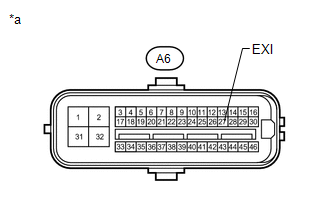
CHECK TERMINAL VOLTAGE (EXI) |
(a) Disconnect the A6 skid control ECU connector.
|
(b) Measure the voltage according to the value(s) in the table below. Standard Voltage:
|
|
|
Result |
Proceed to |
|---|---|
|
OK |
A |
|
NG (for Part-time 4WD) |
B |
|
NG (for Full-time 4WD) |
C |
| B | .gif) |
GO TO STEP 3 |
| C | |
GO TO STEP 4 |
|
.gif)
|
2. |
RECONFIRM DTC |
(a) Clear the DTCs (See page ).
(b) Check for DTCs (See page ).
Result
|
Result |
Proceed to |
|---|---|
|
DTC is output |
A |
|
DTC is not output |
B |
| A | |
REPLACE MASTER CYLINDER SOLENOID |
| B | |
USE SIMULATION METHOD TO CHECK |
|
3. |
CHECK HARNESS AND CONNECTOR (SKID CONTROL ECU - FOUR WHEEL DRIVE CONTROL ECU AND A.D.D. ACTUATOR) |
(a) Disconnect the A6 skid control ECU connector.
(b) Disconnect the F47 four wheel drive control ECU connector.
(c) Disconnect the D1 A.D.D. actuator connector.
(d) Measure the resistance according to the value(s) in the table below.
Standard Resistance:
w/ Rear Differential Lock|
Tester Connection |
Condition |
Specified Condition |
|---|---|---|
|
A6-27 (EXI) - F47-15 (ADD) |
Always |
Below 1 Ω |
|
A6-27 (EXI) - D1-3 (ADD) |
Always |
Below 1 Ω |
|
A6-27 (EXI) - Body ground |
Always |
10 kΩ or higher |
|
D1-4 (GND) - Body ground |
Always |
Below 1 Ω |
:
w/o Rear Differential Lock|
Tester Connection |
Condition |
Specified Condition |
|---|---|---|
|
A6-27 (EXI) - F47-14 (ADD) |
Always |
Below 1 Ω |
|
A6-27 (EXI) - D1-3 (ADD) |
Always |
Below 1 Ω |
|
A6-27 (EXI) - Body ground |
Always |
10 kΩ or higher |
|
D1-4 (GND) - Body ground |
Always |
Below 1 Ω |
| OK | |
GO TO TRANSFER SYSTEM (PROBLEM SYMPTOMS TABLE) |
| NG | |
REPAIR OR REPLACE HARNESS OR CONNECTOR |
|
4. |
CHECK HARNESS AND CONNECTOR (SKID CONTROL ECU - FOUR WHEEL DRIVE CONTROL ECU AND TRANSFER SHIFT ACTUATOR ASSEMBLY) |
(a) Disconnect the A6 skid control ECU connector.
(b) Disconnect the F47 four wheel drive control ECU connector.
(c) Disconnect the B47 transfer shift actuator assembly connector.
(d) Measure the resistance according to the value(s) in the table below.
Standard Resistance:
|
Tester Connection |
Condition |
Specified Condition |
|---|---|---|
|
A6-27 (EXI) - F47-14 (P1) |
Always |
Below 1 Ω |
|
A6-27 (EXI) - B47-9 (CDL) |
Always |
Below 1 Ω |
|
A6-27 (EXI) - Body ground |
Always |
10 kΩ or higher |
|
B47-10 (GND) - Body ground |
Always |
Below 1 Ω |
| OK | |
GO TO TRANSFER SYSTEM (PROBLEM SYMPTOMS TABLE) |
| NG | |
REPAIR OR REPLACE HARNESS OR CONNECTOR |
 Power Supply Drive Circuit (C1257)
DESCRIPTION
The motor relay (semiconductor relay) is built into the master cylinder solenoid
and drives the pump motor based on a signal from the skid control ECU.
DTC Code
D ...
 Transfer L4 Position Switch Circuit (C1268)
DESCRIPTION
DTC Code
DTC Detection Condition
Trouble Area
C1268
The skid control ECU receives an L4 abnormal status signal from the four
...
Other materials about Toyota 4Runner:
Power Seat Position is not Memorized
DESCRIPTION
When the seat memory SET switch and a memory switch (M1 or M2) are pressed simultaneously,
the main body ECU commands the position control ECU through CAN communication to
record the value of each position sensor.
WIRING DIAGRAM
CAUTION / ...
Rear Washer does not Operate
DESCRIPTION
The windshield wiper switch controls the rear washer motor and pump.
WIRING DIAGRAM
CAUTION / NOTICE / HINT
NOTICE:
Inspect the fuses for circuits related to this system before performing the following
inspection procedure.
PROCEDURE
...
0.0123