Toyota 4Runner: Outer Mirror Switch
Components
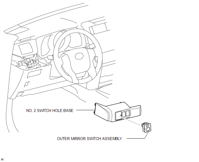
COMPONENTS
ILLUSTRATION
Removal
REMOVAL
PROCEDURE
1. REMOVE NO. 2 SWITCH HOLE BASE
.gif)
2. REMOVE OUTER MIRROR SWITCH ASSEMBLY
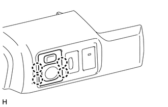
(a) Using a screwdriver, detach the 4 claws and remove the switch.
HINT:
Tape the screwdriver tip before use.
Inspection
INSPECTION
PROCEDURE
1. INSPECT OUTER MIRROR SWITCH ASSEMBLY
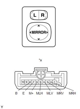
(a) Inspect the outer mirror switch assembly.
(1) Select "L" on the left/right adjustment switch.
(2) Measure the resistance according to the value(s) in the table below.
Standard Resistance:
|
Tester Connection |
Switch Condition |
Specified Condition |
|
|---|---|---|---|
|
4 (MLV) - 8 (B) 6 (M+) - 7 (E) |
UP |
Pressed |
Below 1 Ω |
|
Not pressed |
10 kΩ or higher |
||
|
4 (MLV) - 7 (E) 6 (M+) - 8 (B) |
DOWN |
Pressed |
Below 1 Ω |
|
Not pressed |
10 kΩ or higher |
||
|
5 (MLH) - 8 (B) 6 (M+) - 7 (E) |
LEFT |
Pressed |
Below 1 Ω |
|
Not pressed |
10 kΩ or higher |
||
|
5 (MLH) - 7 (E) 6 (M+) - 8 (B) |
RIGHT |
Pressed |
Below 1 Ω |
|
Not pressed |
10 kΩ or higher |
||
If the result is not as specified, replace the outer mirror switch assembly.
(3) Select "R" on the left/right adjustment switch.
(4) Measure the resistance according to the value(s) in the table below.
Standard Resistance:
|
Tester Connection |
Switch Condition |
Specified Condition |
|
|---|---|---|---|
|
3 (MRV) - 8 (B) 6 (M+) - 7 (E) |
UP |
Pressed |
Below 1 Ω |
|
Not pressed |
10 kΩ or higher |
||
|
3 (MRV) - 7 (E) 6 (M+) - 8 (B) |
DOWN |
Pressed |
Below 1 Ω |
|
Not pressed |
10 kΩ or higher |
||
|
2 (MRH) - 8 (B) 6 (M+) - 7 (E) |
LEFT |
Pressed |
Below 1 Ω |
|
Not pressed |
10 kΩ or higher |
||
|
2 (MRH) - 7 (E) 6 (M+) - 8 (B) |
RIGHT |
Pressed |
Below 1 Ω |
|
Not pressed |
10 kΩ or higher |
||
If the result is not as specified, replace the outer mirror switch assembly.
Text in Illustration|
*a |
Component without harness connected (Outer Mirror Switch Assembly) |
Installation
INSTALLATION
PROCEDURE
1. INSTALL OUTER MIRROR SWITCH ASSEMBLY
(a) Attach the 2 claws to install the switch.
2. INSTALL NO. 2 SWITCH HOLE BASE
.gif)
 Mirror (ext)
...

Other materials about Toyota 4Runner:
Operating Light Control Rheostat does not Change Light Brightness
DESCRIPTION
When the light control rheostat dial is turned upward, the combination meter
and vehicle interior illumination will become brighter. When the light control rheostat
dial is turned downward, the combination meter and vehicle illumination will d ...
Clearance Warning Buzzer
Components
COMPONENTS
ILLUSTRATION
Removal
REMOVAL
PROCEDURE
1. REMOVE INSTRUMENT PANEL SUB-ASSEMBLY
(a) Remove the instrument panel sub-assembly (See page
).
2. REMOVE NO. 1 CLEARANCE WARNING BUZZER
(a) Disconnect the connector.
(b) Detach ...
0.026