Toyota 4Runner: Personal Light(for Front Door)
Components
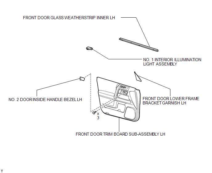
COMPONENTS
ILLUSTRATION
Inspection
INSPECTION
PROCEDURE
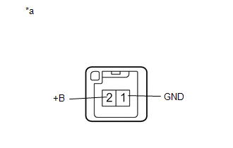
1. INSPECT NO. 1 INTERIOR ILLUMINATION LIGHT ASSEMBLY
|
(a) Apply battery voltage to the connector and check the LED illumination. OK:
If the result is not as specified, replace the No. 1 interior illumination light assembly. Text in Illustration
|
|
Installation
INSTALLATION
CAUTION / NOTICE / HINT
HINT:
- Use the same procedure for the RH and LH sides.
- The procedure listed below is for the LH side.
PROCEDURE
1. INSTALL NO. 1 INTERIOR ILLUMINATION LIGHT ASSEMBLY
|
(a) Connect the connector. |
|
(b) Attach the claw to install the light.
2. INSTALL FRONT DOOR GLASS WEATHERSTRIP INNER LH
.gif)
3. INSTALL FRONT DOOR TRIM BOARD SUB-ASSEMBLY LH
4. INSTALL NO. 2 DOOR INSIDE HANDLE BEZEL LH
5. INSTALL FRONT DOOR LOWER FRAME BRACKET GARNISH LH
Removal
REMOVAL
CAUTION / NOTICE / HINT
HINT:
- Use the same procedure for the RH and LH sides.
- The procedure listed below is for the LH side.
PROCEDURE
1. REMOVE FRONT DOOR LOWER FRAME BRACKET GARNISH LH
.gif)
2. REMOVE NO. 2 DOOR INSIDE HANDLE BEZEL LH
3. REMOVE FRONT DOOR TRIM BOARD SUB-ASSEMBLY LH
4. REMOVE FRONT DOOR GLASS WEATHERSTRIP INNER LH
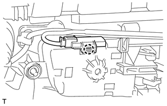
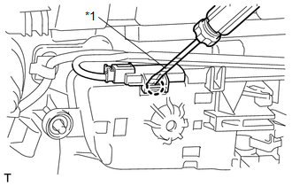
5. REMOVE NO. 1 INTERIOR ILLUMINATION LIGHT ASSEMBLY
|
(a) Using a screwdriver, detach the claw and remove the light. HINT: Tape the screwdriver tip before use. Text in Illustration
|
|
(b) Disconnect the connector.
 Luggage Compartment Room Light
Components
COMPONENTS
ILLUSTRATION
Removal
REMOVAL
CAUTION / NOTICE / HINT
HINT:
Use the same procedure for the RH and LH sides.
The procedure listed below is for the LH side. ...
 Personal Light(for Rear Door)
Components
COMPONENTS
ILLUSTRATION
Removal
REMOVAL
CAUTION / NOTICE / HINT
HINT:
Use the same procedure for the RH and LH sides.
The procedure listed below is for the LH side. ...
Other materials about Toyota 4Runner:
On-vehicle Inspection
ON-VEHICLE INSPECTION
CAUTION / NOTICE / HINT
HINT:
Use the same procedure for the RH and LH sides.
The procedure listed below is for the LH side.
PROCEDURE
1. CHECK SIDE AIRBAG SENSOR ASSEMBLY LH (VEHICLE NOT INVOLVED IN COLLISION)
(a) ...
Key-off Operation Function Operates even if Operating Conditions are not Satisfied
DESCRIPTION
When the front doors are closed, each power window regulator motor can
control its power window operation for approximately 43 seconds after the
ignition switch is turned from ON to off by receiving operation permission
signals ...
0.0071