Toyota 4Runner: Pressure Control Solenoid "D" Electrical (Shift Solenoid Valve SLT) (P2716)
DESCRIPTION
Refer to DTC P2714 (See page .gif) ).
).
|
DTC Code |
DTC Detection Condition |
Trouble Area |
|---|---|---|
|
P2716 |
Open or short is detected in the shift solenoid valve SLT circuit for 1 sec. or more while driving (1-trip detection logic). |
|
MONITOR DESCRIPTION
When an open or short in the shift solenoid valve (SLT) circuit is detected, the ECM interprets this as a fault. The ECM will turn on the MIL and store the DTC.
MONITOR STRATEGY
|
Related DTCs |
P2716: Shift solenoid valve SLT/Range check |
|
Required sensors/Components |
Shift solenoid valve SLT |
|
Frequency of operation |
Continuous |
|
Duration |
1 sec. |
|
MIL operation |
Immediate |
|
Sequence of operation |
None |
TYPICAL ENABLING CONDITIONS
|
The monitor will run whenever the following DTCs are not stored |
None |
|
Battery voltage |
11 V or higher |
|
Ignition switch |
ON |
|
Starter |
OFF |
|
Solenoid current cut status |
Not cut |
|
Target duty cycle |
19% or more |
TYPICAL MALFUNCTION THRESHOLDS
|
Solenoid voltage monitor signal from solenoid driver MIC |
No signal |
COMPONENT OPERATING RANGE
|
Output signal duty |
Less than 100% |
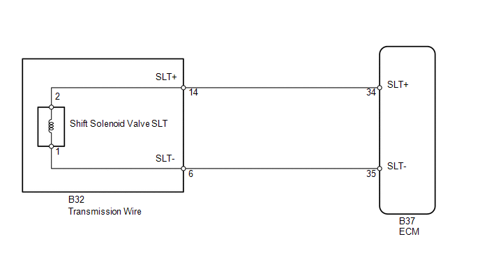
WIRING DIAGRAM
CAUTION / NOTICE / HINT
NOTICE:
Perform the universal trip to clear permanent DTCs (See page
).
PROCEDURE
|
1. |
INSPECT TRANSMISSION WIRE (SHIFT SOLENOID VALVE SLT) |
|
(a) Disconnect the B32 transmission wire connector. |
|
(b) Measure the resistance according to the value(s) in the table below.
Standard Resistance:
|
Tester Connection |
Condition |
Specified Condition |
|---|---|---|
|
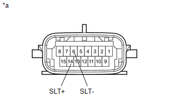
14 (SLT+) - 6 (SLT-) |
20°C (68°F) |
5.0 to 5.6 Ω |
|
14 (SLT+) - Body ground |
Always |
10 kΩ or higher |
|
6 (SLT-) - Body ground |
Always |
10 kΩ or higher |
|
*a |
Component without harness connected (Transmission Wire) |
| NG | .gif) |
GO TO STEP 3 |
|
.gif)
|
2. |
CHECK HARNESS AND CONNECTOR (TRANSMISSION WIRE - ECM) |
|
(a) Disconnect the B37 ECM connector. |
|
(b) Measure the resistance according to the value(s) in the table below.
Standard Resistance:
|
Tester Connection |
Condition |
Specified Condition |
|---|---|---|
|
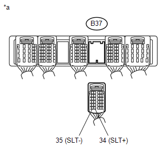
B37-34 (SLT+) - B37-35 (SLT-) |
20°C (68°F) |
5.0 to 5.6 Ω |
|
B37-34 (SLT+) - Body ground |
Always |
10 kΩ or higher |
|
B37-35 (SLT-) - Body ground |
Always |
10 kΩ or higher |
|
*a |
Rear view of wire harness connector (to ECM) |
| OK | |
REPLACE ECM |
| NG | |
REPAIR OR REPLACE HARNESS OR CONNECTOR |
|
3. |
INSPECT SHIFT SOLENOID VALVE SLT |
| OK | |
REPAIR OR REPLACE TRANSMISSION WIRE |
| NG | |
REPLACE SHIFT SOLENOID VALVE SLT |
 Transmission Fluid Temperature Sensor "B" Circuit Low Input (P2742,P2743)
DESCRIPTION
The Automatic Transmission Fluid (ATF) temperature sensor is on the transmission,
just in front of the oil cooler inlet pipeline.
If the ECM detects an abnormally high ATF temperature ...
 Pressure Control Solenoid "D" Performance (Shift Solenoid Valve SLT) (P2714)
DESCRIPTION
The linear solenoid valve (SLT) controls the transmission line pressure for smooth
transmission operation based on signals from the throttle position sensor and vehicle
speed sensor ...
Other materials about Toyota 4Runner:
Cellular Phone Inspection
CAUTION / NOTICE / HINT
HINT:
If the operation of a cellular phone or the navigation receiver assembly is requested,
make sure to follow the instructions closely and perform the operation.
PROCEDURE
1.
CHECK USAGE CONDITION
...
General Maintenance
GENERAL MAINTENANCE
PROCEDURE
1. INSPECT STEERING LINKAGE AND GEAR HOUSING
(a) Check the steering wheel free play.
(b) Check the steering linkage for looseness or damage.
(1) Check that the tie rod ends do not have excessive play.
(2) Check that the dust ...
0.008