Toyota 4Runner: Reassembly
REASSEMBLY
PROCEDURE
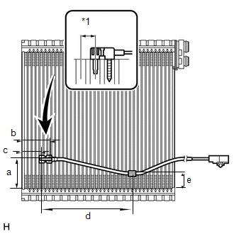
1. INSTALL NO. 1 COOLER THERMISTOR
NOTICE:
If reusing the evaporator, do not insert the thermistor into a location where the thermistor was previously inserted.
(a) Insert the thermistor to a location that is 1 fin to the right or left of its previous location.
Standard:
|
Item |
Specified Condition |
|---|---|
|
a |
50 mm (1.97 in.) |
|
b |
46.7 mm (1.84 in.) |
|
c |
33.3 mm (1.31 in.) |
|
d |
154.1 mm (6.07 in.) |
|
e |
25 mm (0.98 in.) |
|
*1 |
1 Fin |
2. INSTALL NO. 1 COOLER EVAPORATOR SUB-ASSEMBLY
(a) Sufficiently apply compressor oil to 2 new O-rings and the fitting surface of the hose joint.
Compressor oil:
ND-OIL 8 or equivalent
(b) Install the 2 O-rings to the evaporator.
|
(c) Install the evaporator. |
|

(d) Attach the 4 claws to install the unit case.
(e) Install the 6 screws.
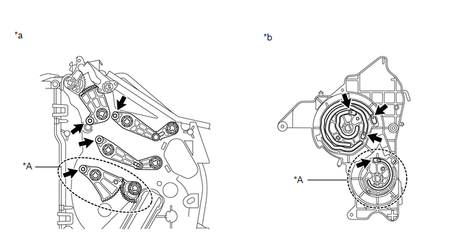
3. INSTALL DAMPER SERVO SUB-ASSEMBLY LH
(a) Align the grooves on the damper servo sub-assembly with the protrusions on the unit and install the damper servo sub-assembly.
 Text in Illustration
|
*A |
for Automatic Air Conditioning System |
- |
- |
|
*a |
Air Conditioning Unit Side |
*b |
Damper Servo Side |
(b) Install the 4 screws.
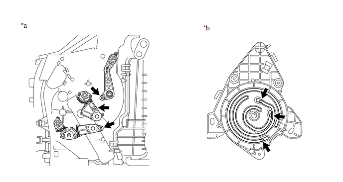
4. INSTALL DAMPER SERVO SUB-ASSEMBLY RH
(a) Align the grooves on the damper servo sub-assembly with the protrusions on the unit and install the damper servo sub-assembly.
 Text in Illustration
|
*a |
Air Conditioning Unit Side |
*b |
Damper Servo Side |
(b) Install the 3 screws.
5. INSTALL COOLER EXPANSION VALVE
(a) Install the expansion valve.
6. INSTALL AIR CONDITIONING TUBE AND ACCESSORY ASSEMBLY
(a) Sufficiently apply compressor oil to 2 new O-rings and the fitting surface of the hose joint.
Compressor oil:
ND-OIL 8 or equivalent
(b) Install the 2 O-rings to the air conditioning tube and accessory assembly.
(c) Install the air conditioning tube and accessory assembly.
(d) Using a 4 mm hexagon wrench, install the 2 hexagon bolts.
Torque:
3.5 N·m {36 kgf·cm, 31 in·lbf}
(e) Install new butyl tape.
(f) Install new packing.
7. INSTALL AIR CONDITIONING HARNESS
(a) Attach the clamps to install the harness.
(b) Connect the connectors.
8. INSTALL HEATER RADIATOR UNIT SUB-ASSEMBLY
(a) Install the radiator.
(b) Install the bracket with the 2 screws.
9. INSTALL QUICK HEATER ASSEMBLY (w/ PTC Heater)
.gif)
10. INSTALL DRAIN COOLER HOSE
|
(a) Install the drain cooler hose as shown in the illustration. |
|
.png)
11. INSTALL ASPIRATOR HOSE
(a) Attach the 2 claws to install the aspirator hose.
12. INSTALL DEFROSTER NOZZLE ASSEMBLY
(a) Attach the 6 claws to install the defroster nozzle assembly.
13. INSTALL BLOWER ASSEMBLY
(a) Attach the 2 claws to install the blower assembly.
(b) Install the screw.
Torque:
2.7 N·m {28 kgf·cm, 24 in·lbf}
 Installation
INSTALLATION
CAUTION / NOTICE / HINT
HINT:
A bolt without a torque specification is shown in the standard bolt chart (See
page ).
PROCEDURE
1. INSTALL INSTRUMENT PANEL REINFORCEMENT ASSEMBLY
...
 Ambient Temperature Sensor
Components
COMPONENTS
ILLUSTRATION
Inspection
INSPECTION
PROCEDURE
1. INSPECT COOLER THERMISTOR (AMBIENT TEMPERATURE SENSOR)
(a) Measure the resistance according to the value(s) in th ...
Other materials about Toyota 4Runner:
Back Sonar Sensor LH Circuit
DESCRIPTION
The ultrasonic sensor sends and receives ultrasonic waves. Based on the received
wave, the sensor calculates the approximate distance between the vehicle and the
obstacle, and sends the distance value as a signal to the clearance warning ECU
...
Installation
INSTALLATION
PROCEDURE
1. INSTALL REAR DIFFERENTIAL CARRIER ASSEMBLY
(a) Remove any dust and oil from the differential carrier assembly and the contact
surfaces of the axle housing.
(b) Install a new gasket and the differential carrier assembly with the ...
0.0259