Toyota 4Runner: Reassembly
REASSEMBLY
PROCEDURE
1. INSTALL SHIFT LOCK CONTROL ECU SUB-ASSEMBLY
(a) Attach the 3 claws to install the shift lock control ECU to the transmission floor shift.
(b) Connect the shift lock solenoid connector to the shift lock control ECU.
2. INSTALL INDICATOR LIGHT WIRE SUB-ASSEMBLY
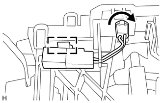
(a) Install the bulb and cap to the indicator light wire.
(b) Align the wire with the key part of the position indicator housing, and install the wire. Then rotate the wire clockwise until it locks.
(c) Attach the connector clamp to the position indicator housing.
3. INSTALL POSITION INDICATOR HOUSING ASSEMBLY
(a) Attach the 4 claws to install the position indicator housing to the transmission floor shift.
4. INSTALL SHIFT LEVER CAP
 Installation
INSTALLATION
PROCEDURE
1. INSTALL NO. 1 CONSOLE BOX MOUNTING BRACKET
(a) Install the console box mounting bracket with the 2 screws.
2. INSTALL SHIFT LEVER ASSEMBLY
(a) Install the transmission ...
 Speed Sensor
Components
COMPONENTS
ILLUSTRATION
Removal
REMOVAL
PROCEDURE
1. REMOVE SPEED SENSOR NT
(a) Disconnect the sensor connector.
(b) Remove the bolt and sensor.
(c) Remove the O-ring from ...
Other materials about Toyota 4Runner:
Installation
INSTALLATION
PROCEDURE
1. INSTALL FRONT DIFFERENTIAL CARRIER ASSEMBLY
(a) Install the front No. 3 differential support with the 2 bolts.
Torque:
108 N·m {1101 kgf·cm, 80 ft·lbf}
(b) Install the front No. 2 differential support with the 2 bolts.
Torq ...
Power Seat Position is not Memorized
DESCRIPTION
When the seat memory SET switch and a memory switch (M1 or M2) are pressed simultaneously,
the main body ECU commands the position control ECU through CAN communication to
record the value of each position sensor.
WIRING DIAGRAM
CAUTION / ...
0.0076