Toyota 4Runner: Reassembly
REASSEMBLY
PROCEDURE
1. INSTALL FRONT PROPELLER SHAFT UNIVERSAL JOINT SPIDER BEARING
HINT:
Use the same procedure for all propeller shaft universal joint spider bearing.
|
(a) Apply MP grease to a new spider and spider bearing. NOTICE: Be careful not to apply too much grease. |
|
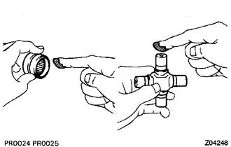
(b) Install the universal joint spider to the propeller shaft.
|
(c) Using SST, install 2 of the spider bearings to the universal joint spider. SST: 09332-25010 |
|
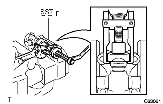
(d) Using SST, adjust both bearings so that the snap ring grooves are at maximum and equal width.
SST: 09332-25010
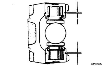
(e) Install 4 new snap rings of equal thickness which will allow no axial play.
HINT:
Do not reuse the snap rings.
Thickness of snap ring:
|
Parts No. |
Specified Condition |
Mark |
|---|---|---|
|
90520-25039 |
2.28 to 2.30 mm (0.0898 to 0.0906 in.) |
1 |
|
90520-25040 |
2.30 to 2.32 mm (0.0906 to 0.0913 in.) |
2 |
|
90520-25041 |
2.32 to 2.34 mm (0.0913 to 0.0921 in.) |
- |
|
90520-25042 |
2.34 to 2.36 mm (0.0921 to 0.0929 in.) |
Brown |
|
90520-25043 |
2.36 to 2.38 mm (0.0929 to 0.0937 in.) |
Blue |
|
90520-25044 |
2.38 to 2.40 mm (0.0937 to 0.0945 in.) |
6 |
|
90520-25045 |
2.40 to 2.42 mm (0.0945 to 0.0953 in.) |
7 |
|
90520-25046 |
2.42 to 2.44 mm (0.0953 to 0.0961 in.) |
8 |
|
90520-25047 |
2.44 to 2.46 mm (0.0961 to 0.0969 in.) |
 |
|
90520-25048 |
2.46 to 2.48 mm (0.0969 to 0.0976 in.) |
10 |
|
90520-25049 |
2.48 to 2.50 mm (0.0976 to 0.0984 in.) |
A |
|
90520-25050 |
2.50 to 2.52 mm (0.0984 to 0.0992 in.) |
B |
|
90520-25051 |
2.52 to 2.54 mm (0.0992 to 0.1000 in.) |
C |
|
90520-25052 |
2.54 to 2.56 mm (0.1000 to 0.1008 in.) |
D |
|
90520-25053 |
2.56 to 2.58 mm (0.1008 to 0.1016 in.) |
E |
|
90520-25054 |
2.18 to 2.20 mm (0.858 to 0.0866 in.) |
J |
|
90520-25055 |
2.20 to 2.22 mm (0.0866 to 0.0874 in.) |
K |
|
90520-25056 |
2.22 to 2.24 mm (0.0874 to 0.0882 in.) |
F |
|
90520-25057 |
2.24 to 2.26 mm (0.0882 to 0.0889 in.) |
G |
|
90520-25058 |
2.26 to 2.28 mm (0.0889 to 0.0898 in.) |
H |
NOTICE:
- Must use a new retainer ring.
- Must use retainer rings of the same thickness as possible on both ends.
|
(f) Using a hammer, tap the yoke until there is no clearance between the spider bearing outer race and snap ring. Text in Illustration
HINT: Install a new spider bearing on the sleeve side in the procedure described above. |
|
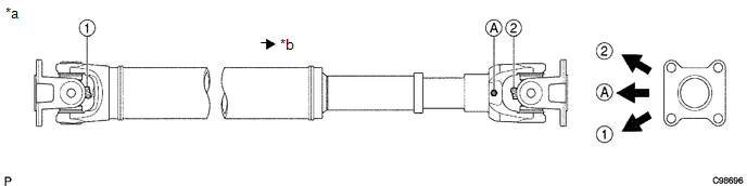
(g) Align the matchmarks on the flange yoke and the sleeve yoke.
|
(h) Using SST, install the spider bearings on the universal joint spider. SST: 09332-25010 |
|
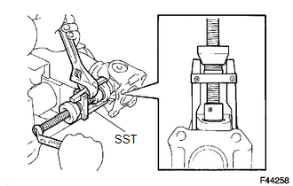
(i) Using SST, adjust both bearings so that the snap ring grooves are at maximum and equal in width.
SST: 09332-25010
(j) Install 4 new snap rings of equal thickness which will allow 0 mm (0 in.) of axial play.
HINT:
Do not reuse the snap rings.
Thickness of snap ring:
|
Parts No. |
Specified Condition |
Mark |
|---|---|---|
|
90520-25039 |
2.28 to 2.30 mm (0.0898 to 0.0906 in.) |
1 |
|
90520-25040 |
2.30 to 2.32 mm (0.0906 to 0.0913 in.) |
2 |
|
90520-25041 |
2.32 to 2.34 mm (0.0913 to 0.0921 in.) |
- |
|
90520-25042 |
2.34 to 2.36 mm (0.0921 to 0.0929 in.) |
Brown |
|
90520-25043 |
2.36 to 2.38 mm (0.0929 to 0.0937 in.) |
Blue |
|
90520-25044 |
2.38 to 2.40 mm (0.0937 to 0.0945 in.) |
6 |
|
90520-25045 |
2.40 to 2.42 mm (0.0945 to 0.0953 in.) |
7 |
|
90520-25046 |
2.42 to 2.44 mm (0.0953 to 0.0961 in.) |
8 |
|
90520-25047 |
2.44 to 2.46 mm (0.0961 to 0.0969 in.) |
|
|
90520-25048 |
2.46 to 2.48 mm (0.0969 to 0.0976 in.) |
10 |
|
90520-25049 |
2.48 to 2.50 mm (0.0976 to 0.0984 in.) |
A |
|
90520-25050 |
2.50 to 2.52 mm (0.0984 to 0.0992 in.) |
B |
|
90520-25051 |
2.52 to 2.54 mm (0.0992 to 0.1000 in.) |
C |
|
90520-25052 |
2.54 to 2.56 mm (0.1000 to 0.1008 in.) |
D |
|
90520-25053 |
2.56 to 2.58 mm (0.1008 to 0.1016 in.) |
E |
|
90520-25054 |
2.18 to 2.20 mm (0.0858 to 0.0866 in.) |
J |
|
90520-25055 |
2.20 to 2.22 mm (0.0866 to 0.0874 in.) |
K |
|
90520-25056 |
2.22 to 2.24 mm (0.0874 to 0.0882 in.) |
F |
|
90520-25057 |
2.24 to 2.26 mm (0.0882 to 0.0890 in.) |
G |
|
90520-25058 |
2.26 to 2.28 mm (0.0890 to 0.0898 in.) |
H |
NOTICE:
- Must use a new retainer ring.
- Must use retainer rings of the same thickness as possible on both ends.
|
(k) Using a plastic faced hammer, tap the yoke until there is no clearance between the spider bearing outer race and snap ring. Text in Illustration
HINT: Install a new spider bearing on the sleeve side in the procedure described above. |
|
2. INSPECT PROPELLER SHAFT ASSEMBLY
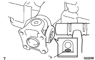
HINT:
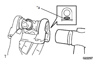
When replacing the spider bearing, be sure that the grease fitting assembly hole is facing to the direction shown in the illustration.
 Text in Illustration
|
*a |
Spider grease fitting assembly direction for front propeller shaft assembly |
*b |
Rear Side |
3. INSPECT FRONT PROPELLER SHAFT UNIVERSAL JOINT SPIDER BEARING
.gif)
 Inspection
INSPECTION
PROCEDURE
1. INSPECT FRONT PROPELLER SHAFT ASSEMBLY
(a) Using a dial indicator, check the propeller shaft runout.
Maximum runout:
0.3 mm (0.0118 in.)
If the shaft ru ...
 Installation
INSTALLATION
PROCEDURE
1. INSTALL FRONT PROPELLER SHAFT ASSEMBLY
(a) Align the matchmarks on the yoke and differential flange.
(b) Install the propeller shaft assembly with the 4 washers, 4 bolts ...
Other materials about Toyota 4Runner:
Removal
REMOVAL
PROCEDURE
1. REMOVE SIDE STEP ASSEMBLY LH
2. REMOVE STABILIZER CONTROL VALVE PROTECTOR
3. DRAIN SUSPENSION FLUID
4. REMOVE REAR STABILIZER LOWER BRACKET
(a) Remove the 4 bolts and 2 rear stabilizer lower brackets.
...
On-vehicle Inspection
ON-VEHICLE INSPECTION
PROCEDURE
1. CHECK LOWER NO. 2 INSTRUMENT PANEL AIRBAG ASSEMBLY (VEHICLE NOT INVOLVED IN
COLLISION)
(a) Perform a diagnostic system check (See page
).
(b) With the lower No. 2 instrument panel airbag installed on the vehicle, perf ...
0.017