Toyota 4Runner: Removal
REMOVAL
PROCEDURE
1. REMOVE NO. 1 INSTRUMENT CLUSTER FINISH PANEL GARNISH
.gif)
2. REMOVE NO. 2 INSTRUMENT CLUSTER FINISH PANEL GARNISH
3. REMOVE HEATER CONTROL ASSEMBLY
4. REMOVE SHIFT LEVER KNOB SUB-ASSEMBLY
5. REMOVE SHIFT LEVER KNOB SUB-ASSEMBLY (for VF2A)
6. REMOVE UPPER CONSOLE PANEL SUB-ASSEMBLY
7. REMOVE NO. 2 CONSOLE BOX RETAINER
8. REMOVE LOWER CENTER INSTRUMENT CLUSTER FINISH PANEL SUB-ASSEMBLY (w/ Climate Control Seat System)
9. REMOVE LOWER CENTER INSTRUMENT CLUSTER FINISH PANEL SUB-ASSEMBLY (w/o Climate Control Seat System)
10. REMOVE POWER OUTLET SOCKET ASSEMBLY
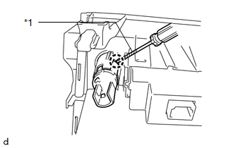
(a) Remove the power outlet socket assembly (w/ Climate Control Seat System).
|
(1) Using a screwdriver, detach the claw to remove the power outlet socket assembly. Text in Illustration
HINT: Tape the screwdriver tip before use. |
|
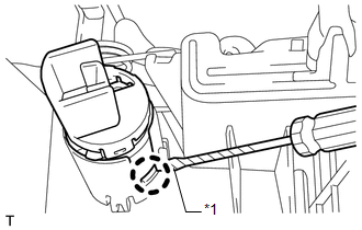
(b) Remove the power outlet socket assembly (w/o Climate Control Seat System).
|
(1) Using a screwdriver, detach the claw to remove the power point socket assembly. Text in Illustration
HINT: Tape the screwdriver tip before use. |
|
11. REMOVE POWER OUTLET SOCKET COVER
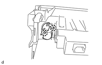
(a) Remove the power outlet socket cover (w/ Climate Control Seat System).
|
(1) Detach the 2 claws to remove the power outlet socket cover. |
|
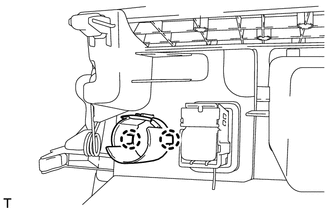
(b) Remove the power outlet socket cover (w/o Climate Control Seat System).
|
(1) Detach the 2 claws to remove the power outlet socket cover. |
|
 Components
COMPONENTS
ILLUSTRATION
ILLUSTRATION
...
 Installation
INSTALLATION
PROCEDURE
1. INSTALL POWER OUTLET SOCKET COVER
(a) Attach the 2 claws to install the socket cover.
2. INSTALL POWER OUTLET SOCKET ASSEMBLY
(a) Attach the claw to install the power ou ...
Other materials about Toyota 4Runner:
Dtc Check / Clear
DTC CHECK / CLEAR
1. DTC CHECK / CLEAR (when Using Techstream)
(a) Check for DTCs.
(1) Connect the Techstream to the DLC3.
(2) Turn the ignition switch to ON.
(3) Turn the Techstream on.
(4) Enter the following menus: Chassis / ABS/VSC/TRAC / Trouble Cod ...
Voice Recognition Microphone Disconnected (B1579)
DESCRIPTION
The navigation receiver assembly and map light assembly (telephone microphone
assembly) are connected to each other using the microphone connection detection
signal lines.
This DTC is stored when a microphone connection detection signal line ...
0.0089