Toyota 4Runner: Inspection
INSPECTION
PROCEDURE
1. INSPECT SEAT HEATER SWITCH LH
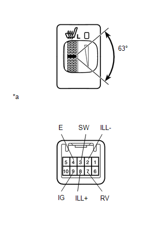
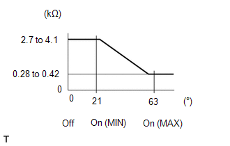
(a) Measure the resistance according to the value(s) in the table below.
Standard Resistance:
|
Tester Connection |
Switch Condition |
Specified Condition |
|---|---|---|
|
3 (SW) - 7 (RV) |
Switch off |
2.7 to 4.1 kΩ |
|
Switch on (Min.) |
||
|
Switch on (Max.) |
0.28 to 0.42 kΩ |
HINT:
As the dial is being turned, the resistance changes gradually.
If the result is not as specified, replace the seat heater switch.
Text in Illustration|
*a |
Component without harness connected (Seat Heater Switch) |
(b) Apply battery voltage to the switch connector, and check that the seat heater switch illuminates.
OK:
|
Measurement Condition |
Specified Condition |
|---|---|
|
Battery positive (+) → 8 (ILL+) Battery negative (-) → 2 (ILL-) |
Illuminates |
If the result is not as specified, replace the seat heater switch.
(c) Apply battery voltage to the switch connector, and check that the seat heater switch indicator illuminates.
OK:
|
Measurement Condition |
Switch Condition |
Specified Condition |
|---|---|---|
|
Battery positive (+) → 9 (IG) Battery negative (-) → 4 (E) |
Switch on |
Indicator illuminates |
If the result is not as specified, replace the seat heater switch.
2. INSPECT SEAT HEATER SWITCH RH
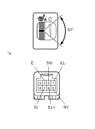
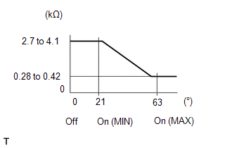
(a) Measure the resistance according to the value(s) in the table below.
Standard Resistance:
|
Tester Connection |
Switch Condition |
Specified Condition |
|---|---|---|
|
2 (SW) - 5 (RV) |
Switch off |
2.7 to 4.1 kΩ |
|
Switch on (Min.) |
||
|
Switch on (Max.) |
0.28 to 0.42 kΩ |
HINT:
As the dial is being turned, the resistance changes gradually.
If the result is not as specified, replace the seat heater switch.
Text in Illustration|
*a |
Component without harness connected (Seat Heater Switch) |
(b) Apply battery voltage to the switch connector, and check that the seat heater switch illuminates.
OK:
|
Measurement Condition |
Specified Condition |
|---|---|
|
Battery positive (+) → 6 (ILL+) Battery negative (-) → 1 (ILL-) |
Illuminates |
If the result is not as specified, replace the seat heater switch.
(c) Apply battery voltage to the switch connector, and check that the seat heater switch indicator illuminates.
OK:
|
Measurement Condition |
Switch Condition |
Specified Condition |
|---|---|---|
|
Battery positive (+) → 7 (IG) Battery negative (-) → 3 (E) |
Switch on |
Indicator illuminates |
If the result is not as specified, replace the seat heater switch.
 Components
COMPONENTS
ILLUSTRATION
...
 Removal
REMOVAL
PROCEDURE
1. REMOVE SHIFT LEVER KNOB SUB-ASSEMBLY
2. REMOVE SHIFT LEVER KNOB SUB-ASSEMBLY (for VF2A)
3. REMOVE UPPER CONSOLE PANEL SUB-ASSEMBLY
4. REMOVE SEAT HEATER SWITCH
...
Other materials about Toyota 4Runner:
Precaution
PRECAUTION
1. NOTICE FOR INITIALIZATION
NOTICE:
When disconnecting the cable from the negative (-) battery terminal, some systems
need to be initialized after the cable is reconnected (See page
).
2. PRECAUTIONS FOR PUSH-BUTTON START FUNCTION
(a) Befo ...
Data List / Active Test
DATA LIST / ACTIVE TEST
1. DATA LIST
NOTICE:
In the table below, the valves listed under "Normal Condition" are reference
values. Do not depend solely on these reference values when deciding whether a part
is faulty or not.
HINT:
Using the T ...
0.0092