Toyota 4Runner: Removal
REMOVAL
PROCEDURE
1. REMOVE NO. 1 ENGINE UNDER COVER SUB-ASSEMBLY
.gif)
2. REMOVE REAR ENGINE UNDER COVER ASSEMBLY
3. REMOVE FRONT FENDER APRON SEAL RH
4. REMOVE FRONT NO. 1 FENDER APRON TO FRAME SEAL RH
5. REMOVE NO. 1 OIL COOLER INLET HOSE AND NO. 1 OIL COOLER OUTLET HOSE
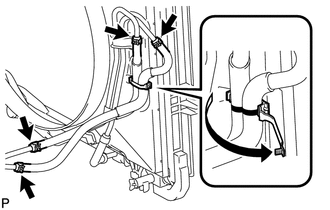
(a) Detach the claw to open the No. 1 flexible hose clamp.
(b) Disconnect the No. 1 oil cooler inlet hose and No. 1 oil cooler outlet hose from the No. 2 oil cooler tube.
(c) Disconnect the 2 hoses from the oil cooler inlet tube and No. 1 oil cooler outlet tube and remove them.
NOTICE:
When disconnecting the hoses from the tube, support the tube by hand and be careful to prevent the tube from being deformed.
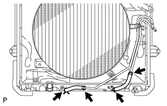
6. REMOVE NO. 1 OIL COOLER INLET TUBE AND NO. 1 OIL COOLER OUTLET TUBE
|
(a) Using a union nut wrench, disconnect the No. 1 oil cooler inlet tube and No. 1 oil cooler outlet tube from each oil cooler tube union. |
|
.png)
(b) Remove the 2 bolts to open the 2 No. 2 flexible hose clamps and remove the 2 oil cooler tubes.
(c) Remove the 2 bolts and 2 No. 2 flexible hose clamps.
7. REMOVE NO. 2 OIL COOLER INLET HOSE AND NO. 2 OIL COOLER OUTLET HOSE
(a) Disconnect the No. 2 oil cooler inlet hose and No. 2 oil cooler outlet hose from the radiator.
(b) Disconnect the 2 hoses from the No. 2 oil cooler tube and remove them.
NOTICE:
When disconnecting the hoses from the tube, support the tube by hand and be careful to prevent the tube from being deformed.
8. REMOVE NO. 2 OIL COOLER TUBE SUB-ASSEMBLY
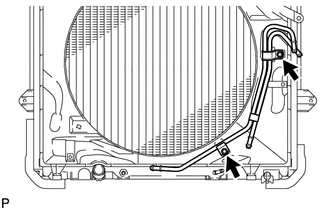
(a) Remove the 2 bolts and No. 2 oil cooler tube.
 Installation
INSTALLATION
PROCEDURE
1. INSTALL NO. 2 OIL COOLER TUBE SUB-ASSEMBLY
(a) Temporarily install the oil cooler tube to the fan shroud with bolt
A. Install bolt B and tighten it to the s ...
 Oil Pump
...
Other materials about Toyota 4Runner:
On-vehicle Inspection
ON-VEHICLE INSPECTION
PROCEDURE
1. CHECK LOWER NO. 1 INSTRUMENT PANEL AIRBAG ASSEMBLY (VEHICLE NOT INVOLVED IN
COLLISION)
(a) Perform a diagnostic system check (See page
).
(b) With the lower No. 1 instrument panel airbag installed on the vehicle, perf ...
Body
General Maintenance
GENERAL MAINTENANCE
PROCEDURE
1. TIGHTEN BOLTS AND NUTS ON CHASSIS AND BODY
(a) Where necessary, tighten all the parts of the chassis.
Front axle and suspension
Drivetrain
Rear axle and suspension
Brake system
...
0.0165