Toyota 4Runner: Removal
REMOVAL
PROCEDURE
1. DISCONNECT CABLE FROM NEGATIVE BATTERY TERMINAL
NOTICE:
When disconnecting the cable, some systems need to be initialized after the cable
is reconnected (See page .gif) ).
).
2. DISCONNECT CABLE FROM POSITIVE BATTERY TERMINAL
3. REMOVE BATTERY CLAMP
|
(a) Loosen the 2 nuts and remove the battery clamp. |
|
4. REMOVE BATTERY
5. REMOVE BATTERY TRAY
6. REMOVE V-BANK COVER
7. REMOVE FAN AND GENERATOR V BELT
8. REMOVE NO. 2 IDLER PULLEY SUB-ASSEMBLY
|
(a) for Integrated Type: Remove the bolt and No. 2 idler pulley. |
|
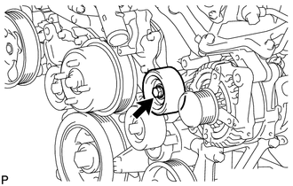
(b) for Separate Type:
Remove the bolt, No. 2 idler pulley cover plate, No. 2 idler pulley and idler pulley cover plate.
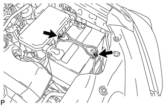
9. REMOVE WIRING HARNESS CLAMP BRACKET
|
(a) Detach the clamp. |
|
(b) Remove the bolt and wiring harness clamp bracket.
10. REMOVE NO. 2 EXHAUST MANIFOLD HEAT INSULATOR
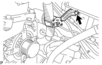
11. REMOVE GENERATOR ASSEMBLY
|
(a) Open the terminal cap. |
|
(b) Remove the nut and disconnect the wire harness from terminal B.
(c) Disconnect the generator connector from the generator assembly.
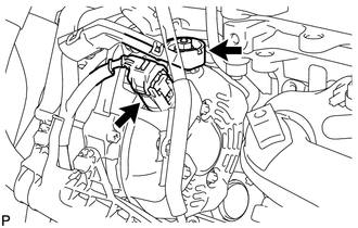
|
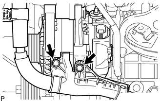
(d) Remove the 2 bolts and disconnect the wire harness. |
|
|
(e) Disconnect the wire harness clamp. |
|
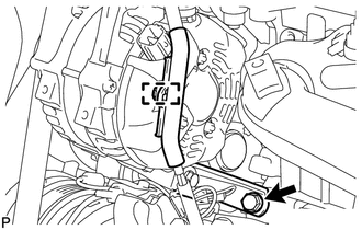
(f) Remove the bolt and disconnect the generator bracket.
|
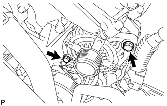
(g) Remove the 2 bolts and generator assembly. |
|
|
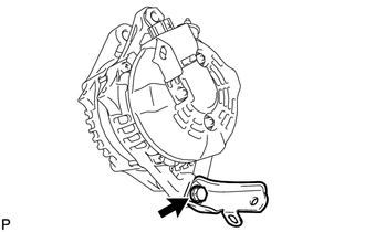
(h) Remove the bolt and generator bracket. |
|
 Components
COMPONENTS
ILLUSTRATION
ILLUSTRATION
...
 Disassembly
DISASSEMBLY
PROCEDURE
1. REMOVE GENERATOR PULLEY CAP
(a) Using a screwdriver, remove the generator pulley cap.
2. REMOVE GENERATOR WITH CLUTCH ...
Other materials about Toyota 4Runner:
Operation Check
OPERATION CHECK
1. CHECK SEAT CUSHION CLIMATE CONTROL BLOWER
(a) Turn the engine switch on (IG).
(b) Set the refreshing seat switch blower side to level 3 (maximum).
(c) Check that the fan motor turns smoothly.
2. CHECK SEATBACK CLIMATE CONTROL BLOWER
(a ...
Alarm
The system sounds the alarm and flashes the lights when forced entry is
detected.
Triggering of the alarm
The alarm is triggered in the following situations when the alarm is set:
• A locked door is unlocked or opened in any way other than using the ...
0.0081