Toyota 4Runner: Solar Sensor
Components
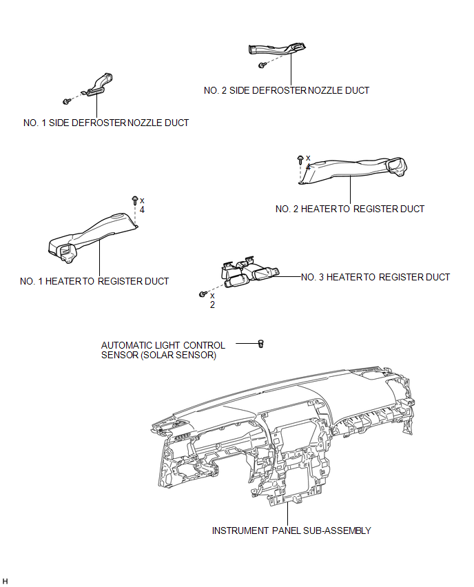
COMPONENTS
ILLUSTRATION
Inspection
INSPECTION
PROCEDURE
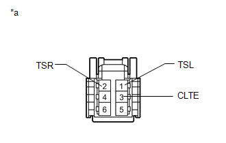
1. INSPECT AUTOMATIC LIGHT CONTROL SENSOR (SOLAR SENSOR)
|
(a) Connect the positive (+) lead of the battery to terminal 6 and the negative (-) lead to terminal 3, and then measure the voltage according to the value(s) in the table below. Standard Voltage:
HINT:
NOTICE: The connection procedure for using a digital tester, such as a TOYOTA electrical tester, is shown above. If the result is not as specified, replace the automatic light control sensor. Text in Illustration
|
|
Removal
REMOVAL
PROCEDURE
1. REMOVE INSTRUMENT PANEL SUB-ASSEMBLY
(a) Remove the instrument panel sub-assembly (See page
.gif) ).
).
2. REMOVE NO. 1 HEATER TO REGISTER DUCT
3. REMOVE NO. 2 HEATER TO REGISTER DUCT
4. REMOVE NO. 1 SIDE DEFROSTER NOZZLE DUCT
5. REMOVE NO. 2 SIDE DEFROSTER NOZZLE DUCT
6. REMOVE NO. 3 HEATER TO REGISTER DUCT
7. REMOVE AUTOMATIC LIGHT CONTROL SENSOR (SOLAR SENSOR)
.png)
(a) Disconnect the connector.
(b) Detach the 2 claws and remove the sensor.
Installation
INSTALLATION
PROCEDURE
1. INSTALL AUTOMATIC LIGHT CONTROL SENSOR (SOLAR SENSOR)
.png)
(a) Attach the 2 claws to install the sensor.
(b) Connect the connector.
2. INSTALL NO. 3 HEATER TO REGISTER DUCT
.gif)
3. INSTALL NO. 2 SIDE DEFROSTER NOZZLE DUCT
4. INSTALL NO. 1 SIDE DEFROSTER NOZZLE DUCT
5. INSTALL NO. 2 HEATER TO REGISTER DUCT
6. INSTALL NO. 1 HEATER TO REGISTER DUCT
7. INSTALL INSTRUMENT PANEL SUB-ASSEMBLY
(a) Install the instrument panel sub-assembly (See page
).
 Room Temperature Sensor
Components
COMPONENTS
ILLUSTRATION
Removal
REMOVAL
PROCEDURE
1. DISCONNECT CABLE FROM NEGATIVE BATTERY TERMINAL
NOTICE:
When disconnecting the cable, some systems need to be initialized ...

Other materials about Toyota 4Runner:
Sound Quality is Bad Only when CD is Played (Volume is Too Low)
PROCEDURE
1.
REPLACE CD AND RECHECK
(a) Replace the CD with a known good one and check that the malfunction disappears.
OK:
Malfunction disappears.
OK
END
NG
REPLACE RADIO AN ...
Voice Guidance does not Function
CAUTION / NOTICE / HINT
NOTICE:
After replacing the navigation receiver assembly of vehicles subscribed to pay-type
satellite radio broadcasts, registration of the XM radio ID is necessary.
PROCEDURE
1.
CHECK VOICE GUIDANCE
...
0.0137