Toyota 4Runner: System Description
SYSTEM DESCRIPTION
1. GENERAL
(a) The air conditioning system has the following controls.
|
Control |
Outline |
|---|---|
|
Neural Network Control |
This control is capable of performing complex control by artificially simulating the information processing method of the nervous system of living organisms in order to establish a complex input/output relationship similar to that of a human brain. |
|
Outlet Air Temperature Control |
Based on the temperature set by the temperature control dial, neural network control calculates outlet air temperature based on input signals from various sensors. |
|
Left and Right Independent Control |
The temperature settings for the driver and front passenger are controlled independently in order to provide separate vehicle interior temperatures for the right and left sides of the vehicle. |
|
Blower Control |
Controls the blower motor in accordance with the airflow volume that has been calculated by neural network control based on the input signals from various sensors. |
|
Air Outlet Control |
Automatically switches the air outlets in accordance with the outlet mode that has been calculated by neural network control. |
|
In accordance with the engine coolant temperature, ambient air temperature, amount of sunlight, required blower speed, outlet temperature and vehicle speed conditions, this control automatically switches the blower outlet to foot and defroster mode to prevent the windows from becoming fogged up when the ambient air temperature is low. |
|
|
Air Inlet Control |
Automatically controls the air inlet control damper to help achieve the calculated outlet air temperature that is required. |
|
Drives the air inlet control servo motor according to the operation of the air inlet control switch and moves the dampers to the fresh or recirculation position. |
|
|
Compressor Control |
The air conditioning amplifier assembly compares the A/C pulley speed signals, which are transmitted by the ECM (crankshaft position sensor). When the air conditioning amplifier assembly determines that the A/C pulley is locked, it turns off the magnet clutch assembly. |
|
Defroster Control |
Defroster control logic is used to improve defroster performance. |
|
Rear Defogger Control |
When the ignition switch is ON and the rear defogger switch is pushed, the system is activated to keep the defogger heater on for approx. 15 minutes. However, the operating time of the rear defogger can be extended up to approx. 255 minutes when both of the following requirements are met:
|
|
Diagnosis |
A Diagnostic Trouble Code (DTC) is stored in memory when the air conditioning amplifier assembly detects a problem with the air conditioning system. |
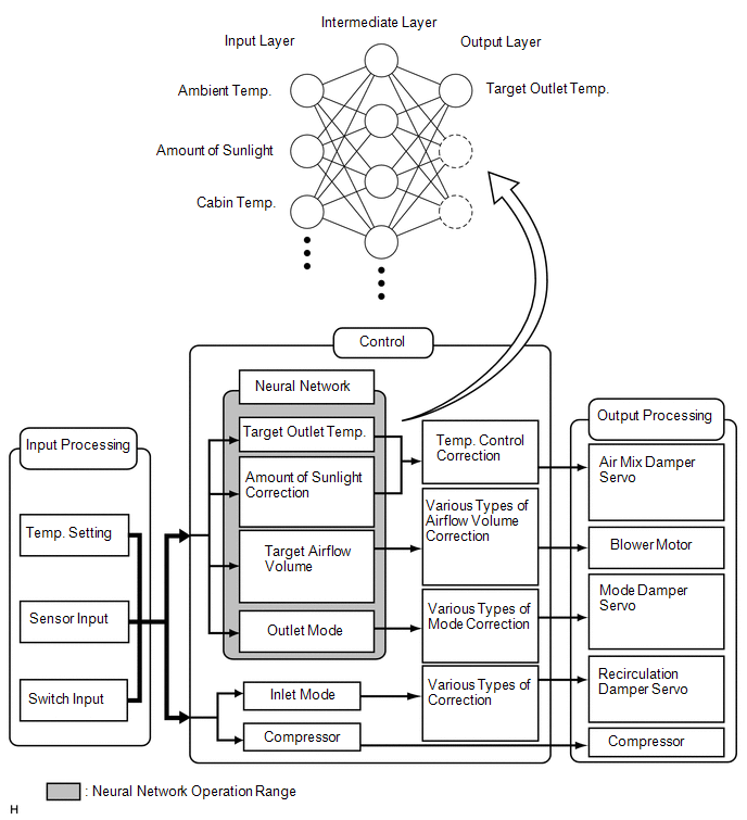
2. NEURAL NETWORK CONTROL
- Neural network control collects data under varying environmental conditions and stores it in the air conditioning amplifier assembly. Neural network control uses this data to enhance air conditioning control.
- Neural network control consists of neurons organized into an input layer, intermediate layer and output layer. The input layer neurons process the input data received from the switches and sensors, which includes the outside temperature, amount of sunlight and room temperature, and outputs this data to the intermediate layer neurons. Based on this data, the intermediate layer neurons adjust the strength of the links among the neurons. The result is then calculated by the output layer neurons in the form of the required outlet temperature, solar correction, target airflow volume and outlet mode control volume. The air conditioning amplifier assembly then controls the servo motors and blower motor in accordance with the control volumes that have been calculated by neural network control.
3. MODE POSITION AND DAMPER OPERATION
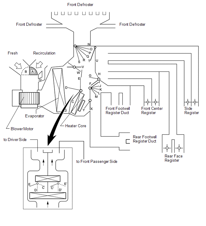 Function of Main Damper
|
Control Damper |
Operation Position |
Damper Position |
Operation |
|---|---|---|---|
|
Air Inlet Control Damper |
Fresh |
A |
Brings in fresh air. |
|
Recirculation |
B |
Recirculates internal air. |
|
|
Air Mix Control Damper |
MAX COOL to MAX HOT |
E - D - C E' - D' - C' |
Varies the mixture of cold air and hot air in order to regulate the temperature continuously from hot to cool. |
|
MAX COOL Damper |
MAX COOL |
V |
Open in the MAX COOL position. |
|
Except MAX COOL |
W |
Close in all position except MAX COOL position. |
|
|
MAX HOT Damper |
MAX HOT |
Y |
Open in the MAX HOT position. |
|
Except MAX HOT |
X |
Closed in all position except MAX HOT position. |
|
|
Mode Control Damper |
Face  |
F, I, N, T, X (FACE 1) F, J, N, T, X (FACE 2) |
Air blows out of the front center registers, side registers and rear face registers. (FACE 1) Air blows out of the front center registers, side registers and rear face registers. In addition, air blows out slightly from the front and rear footwell register ducts. (FACE 2) |
|
Bi-level  |
G, L, N, T, X |
Air blows out of the front center registers, side registers, rear face registers and front and rear footwell register ducts. |
|
|
Foot  |
H, M, P, T, W, Y (MAX HOT position) H, M, O, T, X (Except MAX HOT Position) |
Air blows out of the front and rear footwell register ducts. In addition, air blows out slightly from the front defroster, side registers, front center registers and rear face registers. |
|
|
Foot/Def  |
H, K, R, T, W, Y (MAX HOT position) H, M, Q, T, X (Except MAX HOT Position) |
Defrosts the windshield through the front defroster and side registers while air is also blown out from the front and rear footwell register ducts. In addition, air blows out slightly from the front center registers and rear face registers. |
|
|
Def  |
H, I, S, U, X |
Defrosts the windshield through the front defrosters. |
4. AIR OUTLETS AND AIRFLOW VOLUME
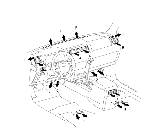
|
Indication (Mode) |
Front Center Register |
Side Register |
Front Footwell Register |
Rear Face Register |
Rear Footwell Register |
Front Defroster |
|---|---|---|---|---|---|---|
|
A |
B |
C |
D |
E |
F |
|
|
Face 1 |
 |
|
- |
 |
- |
- |
|
Face 2 |
|
|
 |
|
|
- |
|
Bi-level |
 |
|
|
|
|
- |
|
Foot |
|
|
|
|
|
|
|
Foot/Def |
|
|
|
|
|
|
|
Def |
- |
- |
- |
- |
- |
|
HINT:
The size of the circle indicates the proportion of airflow volume.
5. A/C LOCK SENSOR
The A/C lock sensor sends A/C pulley speed signals to the air conditioning amplifier assembly. The air conditioning amplifier assembly determines whether the cooler compressor assembly is locked or not by using those signals and engine speed signals.
6. NO. 1 COOLER THERMISTOR
The No. 1 cooler thermistor detects the temperature of the cool air immediately after it passes through the evaporator in the form of resistance changes, and outputs the temperature to the air conditioning amplifier assembly.
7. BLOWER WITH FAN MOTOR SUB-ASSEMBLY
The blower with fan motor sub-assembly has a built-in blower controller and is controlled by the air conditioning amplifier assembly using duty control.
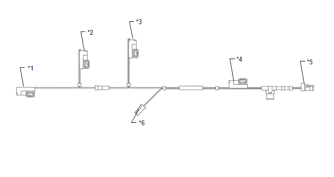
8. AIR CONDITIONING HARNESS ASSEMBLY (BUS CONNECTOR)
(a) A BUS connector is used in the wire harness that connects the servo motor to the air conditioning amplifier assembly.
|
Connector Type |
Connected to |
|---|---|
|
*1: Bus connector |
Damper servo sub-assembly LH (driver side air mix damper servo) |
|
*2: Bus connector |
Damper servo sub-assembly LH (mode damper servo) |
|
*3: Bus connector |
Damper servo sub-assembly RH (front passenger side air mix damper servo) |
|
*4: Bus connector |
Recirculation damper servo sub-assembly |
|
*5: Connector |
Air conditioning amplifier assembly |
|
*6: Connector |
No. 1 cooler thermistor |
(b) Each BUS connector has a built-in communication/driver IC which communicates with each servo motor connector, actuates the servo motor, and has a position detection function.
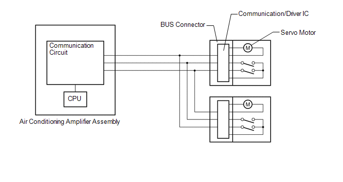
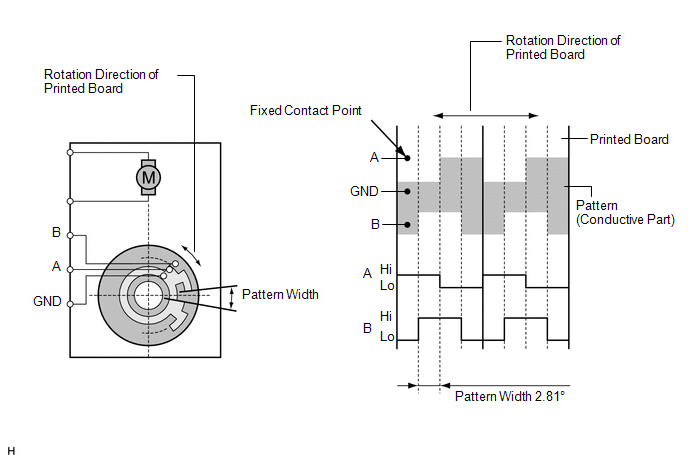
9. SERVO MOTOR
(a) The pulse pattern type servo motor detects the relative position using 2-bit on/off signals.
The forward and reverse revolutions of this motor are detected using two signals, A and B, which output four types of patterns. The air conditioning amplifier assembly counts the number of pulse patterns in order to determine the stopped position.
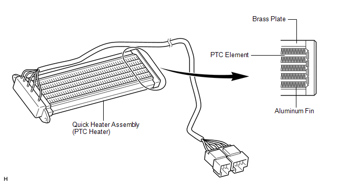
10. QUICK HEATER ASSEMBLY (w/ PTC Heater)
(a) General
(1) The PTC heater is located above the heater core in the air conditioner unit.
(2) The PTC heater consists of a PTC element, aluminum fins and brass plates. When current is applied to the PTC element, it generates heat to warm the air that passes through the unit.
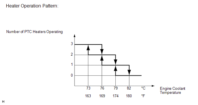
(b) PTC Heater Operating Conditions
(1) The on/off operation of the PTC heater is controlled by the air conditioning amplifier assembly in accordance with the engine coolant temperature, ambient temperature, engine speed, air mix setting and electrical load (generator power ratio).
For example, the number of operating PTC heaters varies according to engine coolant temperature as shown in the graph below.
11. COOLER THERMISTOR (ROOM TEMPERATURE SENSOR)
The cooler thermistor (room temperature sensor) detects the cabin temperature based on changes in the resistance of its built-in thermistor and sends a signal to the air conditioning amplifier assembly.
12. COOLER THERMISTOR (AMBIENT TEMPERATURE SENSOR)
The cooler thermistor (ambient temperature sensor) detects the outside temperature based on changes in the resistance of its built-in thermistor and sends a signal to the air conditioning amplifier assembly.
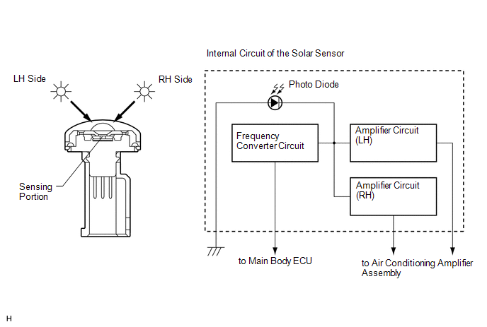
13. AUTOMATIC LIGHT CONTROL SENSOR (SOLAR SENSOR)
(a) The automatic light control sensor (solar sensor) consists of a photo diode, 2 amplifier circuits for the solar sensor and a frequency converter circuit for the light control sensor.
(b) The automatic light control sensor (solar sensor) detects (in the form of changes in the current that flows through the built-in photo diode) the changes in the amount of sunlight from the LH and RH sides (2 directions) and outputs these sunlight intensity signals to the air conditioning amplifier assembly.
 Precaution
PRECAUTION
1. IGNITION SWITCH EXPRESSIONS
HINT:
The type of ignition switch used on this model differs according to the specifications
of the vehicle. The expressions listed in the table below ar ...
 System Diagram
SYSTEM DIAGRAM
Communication Table
Transmitter
Receiver
Signal
Communication Line
Air conditioning amplifier assembly
ECM
...
Other materials about Toyota 4Runner:
Transmitter ID not Received in Main Mode (C2126/26)
DESCRIPTION
After all IDs are registered, DTC C2126/26 is stored in the tire pressure warning
ECU and the tire pressure warning light blinks for 1 minute and then comes on.
When the tire pressure warning ECU successfully receives information from all
the ...
Rear Lower Arm
Components
COMPONENTS
ILLUSTRATION
Removal
REMOVAL
CAUTION / NOTICE / HINT
HINT:
Use the same procedure for the RH and LH sides.
The procedure listed below is for the LH side.
PROCEDURE
1. REMOVE REAR WHEEL
2. DISCONNECT NO. 3 ...
0.0266