Toyota 4Runner: System Diagram
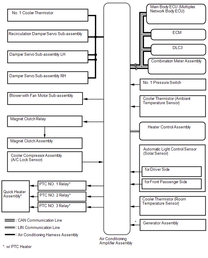
SYSTEM DIAGRAM
 Communication Table
|
Transmitter |
Receiver |
Signal |
Communication Line |
|---|---|---|---|
|
Air conditioning amplifier assembly |
ECM |
A/C idle up request signal |
CAN |
|
Heater idle up request signal |
|||
|
PTC heater control request signal* |
|||
|
Electricity load at low voltage state signal |
|||
|
Ambient temperature signal |
|||
|
Main body ECU |
Air conditioning amplifier assembly |
Main body request signal |
|
|
Combination meter assembly |
Air conditioning amplifier assembly |
Vehicle speed signal |
|
|
ECM |
Air conditioning amplifier assembly |
Engine coolant temperature signal |
|
|
Engine speed data |
|||
|
Engine type information signal |
|||
|
Heater control assembly |
Air conditioning amplifier assembly |
AUTO operation switch signal |
LIN |
|
OFF operation switch signal |
|||
|
A/C switch signal |
|||
|
Front defroster operation switch signal |
|||
|
Rear defogger operation switch signal |
|||
|
Mode operation switch signal |
|||
|
REC/FRS switch signal |
|||
|
Set temperature switch signal |
|||
|
Blower operation switch signal (up, down) |
- *: w/ PTC Heater
 System Description
SYSTEM DESCRIPTION
1. GENERAL
(a) The air conditioning system has the following controls.
Control
Outline
Neural Network Control
This control is ca ...
 How To Proceed With Troubleshooting
CAUTION / NOTICE / HINT
HINT:
Use these procedures to troubleshoot the air conditioning system.
*: Use the Techstream.
PROCEDURE
1.
VEHICLE BROUGHT TO W ...
Other materials about Toyota 4Runner:
Installation
INSTALLATION
PROCEDURE
1. INSTALL WIPER MOTOR WIRE
(a) Attach the claw to install the wiper motor wire.
2. INSTALL WINDSHIELD WIPER MOTOR ASSEMBLY
(a) Using a T30 "TORX" socket, install the wiper motor with the 2 bolts.
Torque:
7.5 N·m {76 k ...
Diagnosis System
DIAGNOSIS SYSTEM
1. DIAGNOSIS SYSTEM
(a) Indicator light
(1) During vehicle stabilizer control operation, the KDSS indicator light comes
on when there is a malfunction in the KDSS.
NOTICE:
When the malfunction has been corrected, the KDSS indica ...
0.0093