Toyota 4Runner: System Diagram
SYSTEM DIAGRAM
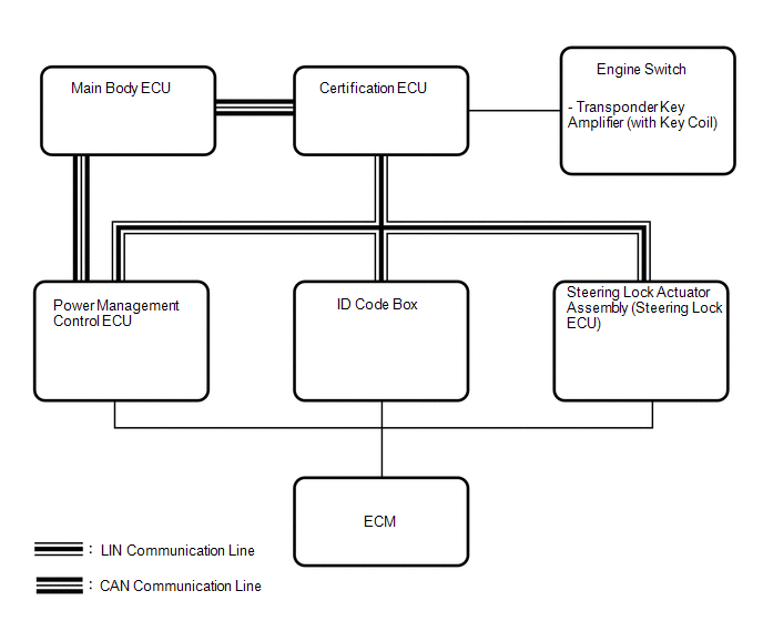 Input and Output Signal of Each ECU
|
Transmitting ECU (Transmitter) |
Receiving ECU (Receiver) |
Signal |
Communication Method |
|---|---|---|---|
|
Power management control ECU |
Steering lock actuator assembly (steering lock ECU) |
Power supply status (to steering lock motor) |
LIN |
|
Steering lock actuator assembly (steering lock ECU) |
|
Sleep available status |
LIN |
|
Steering lock actuator assembly (steering lock ECU) |
|
Lock/unlock sensor status |
LIN |
|
Steering lock actuator assembly (steering lock ECU) |
|
Steering lock status |
LIN |
|
Steering lock actuator assembly (steering lock ECU) |
|
Motor control status |
LIN |
|
Steering lock actuator assembly (steering lock ECU) |
|
Diagnostic response status |
LIN |
|
Steering lock actuator assembly (steering lock ECU) |
|
Lock/unlock sensor malfunction |
LIN |
|
Steering lock actuator assembly (steering lock ECU) |
|
Power supply malfunction (to steering lock motor) |
LIN |
|
Steering lock actuator assembly (steering lock ECU) |
|
Motor driver malfunction |
LIN |
|
Steering lock actuator assembly (steering lock ECU) |
|
Lock bar (stuck) status |
LIN |
|
Steering lock actuator assembly (steering lock ECU) |
|
Push start status |
LIN |
|
Steering lock actuator assembly (steering lock ECU) |
|
Lock/unlock relay drive status |
LIN |
|
Steering lock actuator assembly (steering lock ECU) |
|
Engine start control status |
LIN |
|
Certification ECU |
Steering lock actuator assembly (steering lock ECU) |
Lock/unlock request |
LIN |
|
Main body ECU |
|
Driver side door courtesy switch signal |
CAN |
 System Description
SYSTEM DESCRIPTION
1. DESCRIPTION
(a) The steering lock system locks or unlocks the steering by activating the
steering lock bar with a motor. The steering lock ECU activates the motor based
on ...
 How To Proceed With Troubleshooting
CAUTION / NOTICE / HINT
HINT:
Use the following procedures to troubleshoot the steering lock system.
*: Use the Techstream.
PROCEDURE
1.
VEHICLE BROUGHT ...
Other materials about Toyota 4Runner:
Trailer Tongue Weight
• A recommended tongue weight varies in accordance with the types of trailers
or towing as described below.
• To ensure the recommended values shown below, the trailer must be loaded by
referring to the following instructions.
• Tongue Weight The g ...
All Doors LOCK/UNLOCK Functions do not Operate Via Master Switch, Driver Side
Door Key Cylinder
DESCRIPTION
The main body ECU (multiplex network body ECU) receives switch signals from the
multiplex network master switch, and key-linked switch signals from the front door
lock. The main body ECU (multiplex network body ECU) activates the door lock mot ...
0.0254