Toyota 4Runner: Terminals Of Ecu
TERMINALS OF ECU
1. REAR TELEVISION CAMERA ASSEMBLY

(a) Disconnect the Y2 rear television camera assembly connector.
(b) Measure the voltage according to the value(s) in the table below.
|
Terminal No. (Symbol) |
Wiring Color |
Terminal Description |
Condition |
Specified Condition |
|---|---|---|---|---|
|
Y2-6 (CB+) - Y2-5 (CGND) |
R - BR |
Power source |
Within 60 seconds of turning the ignition switch to ACC |
5.5 to 7.05 V |
(c) Reconnect the Y2 rear television camera assembly connector.
(d) Measure the voltage and check for pulses between each terminal of the connector.
|
Terminal No. (Symbol) |
Wiring Color |
Terminal Description |
Condition |
Specified Condition |
|---|---|---|---|---|
|
Y2-2 (CV-) - Y2-3 (CV+) |
B - W |
Video signal |
Ignition switch ON Shift lever in R Camera lens not covered, displaying an image |
Pulse generation (See waveform 1) |
|
Ignition switch ON Shift lever in R Camera lens covered, blacking out screen |
Pulse generation (See waveform 2) |
|||
|
Y2-5 (CGND) - Body ground |
BR - Body ground |
Ground |
Always |
Below 1 V |
HINT:
- A waterproof connector is used for the rear television camera assembly. Therefore, inspect the waveform at the rear television camera assembly with the connector connected.
- If the result is not as specified, the rear television camera assembly may be malfunctioning.
(e) Reference (Oscilloscope waveform):
HINT:
A waterproof connector is used for the rear television camera assembly. Therefore, inspect the waveform at the rear television camera assembly with the connector connected.
.png)
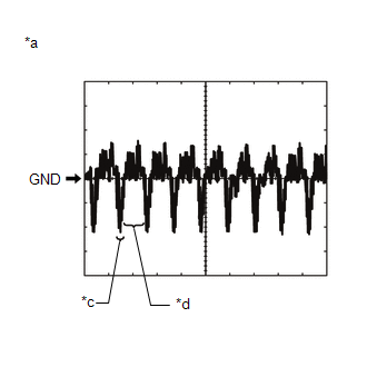
(1) Waveform 1 (camera lens is not covered, displaying an image)
|
Item |
Content |
|---|---|
|
Terminal No. (Symbol) |
Y2-2 (CV-) - Y2-3 (CV+) |
|
Tool Setting |
200 mV/DIV., 50 μsec./DIV. |
|
Condition |
Ignition switch ON, shift lever in R |
HINT:
The video waveform changes according to the image sent by the rear television camera assembly.
(2) Waveform 2 (camera lens is covered, blacking out the screen)
|
Item |
Content |
|---|---|
|
Terminal No. (Symbol) |
Y2-2 (CV-) - Y2-3 (CV+) |
|
Tool Setting |
200 mV/DIV., 50 μsec./DIV. |
|
Condition |
Ignition switch ON, shift lever in R |
HINT:
The video waveform changes according to the image sent by the rear television camera assembly.
Text in Illustration|
*a |
Waveform 1 (camera lens is not covered, displaying an image) |
|
*b |
Waveform 2 (camera lens is covered, blacking out the screen) |
|
*c |
Synchronization Signal |
|
*d |
Video Waveform |
2. NAVIGATION RECEIVER ASSEMBLY (See page .gif) )
)
 Problem Symptoms Table
PROBLEM SYMPTOMS TABLE
HINT:
Use the table below to help determine the cause of problem symptoms.
If multiple suspected areas are listed, the potential causes of the symptoms
are lis ...
 Diagnosis System
DIAGNOSIS SYSTEM
DESCRIPTION
(a) Diagnostic Trouble Codes (DTCs) can be read from the Data Link Connector
3 (DLC3) of the vehicle. When the rear view monitor system seems to be malfunctioning,
u ...
Other materials about Toyota 4Runner:
System Diagram
SYSTEM DIAGRAM
Communication Table
Sender
Receiver
Signal
Line
ECM
Main Body ECU (Multiplex Network Body ECU)
Shift position P signal
Transmission informatio ...
System Diagram
SYSTEM DIAGRAM
Input and Output Signal of Each ECU
Transmitting ECU (Transmitter)
Receiving ECU (Receiver)
Signal
Communication Method
Power management control ECU
Steering lock actuato ...
0.0251