Toyota 4Runner: Tire Pressure Warning Ecu
Components
COMPONENTS
ILLUSTRATION
Installation
INSTALLATION
PROCEDURE
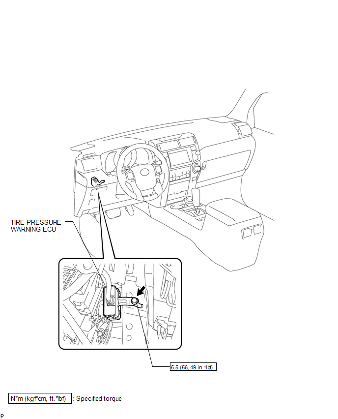
1. INSTALL TIRE PRESSURE WARNING ECU
(a) Install the tire pressure warning ECU with the bolt.
Torque:
5.5 N·m {56 kgf·cm, 49 in·lbf}
(b) Connect the connector.
2. INSTALL LOWER NO. 1 INSTRUMENT PANEL AIRBAG ASSEMBLY
(a) Install the lower No. 1 instrument panel airbag assembly (See page
.gif) ).
).
3. PERFORM REGISTRATION OF TRANSMITTER ID
(a) Perform registration of the transmitter ID (See page
).
Removal
REMOVAL
PROCEDURE
1. REMOVE LOWER NO. 1 INSTRUMENT PANEL AIRBAG ASSEMBLY
(a) Remove the lower No. 1 instrument panel airbag assembly (See page
.gif) ).
).
2. REMOVE TIRE PRESSURE WARNING ECU
|
(a) Disconnect the connector. |
|
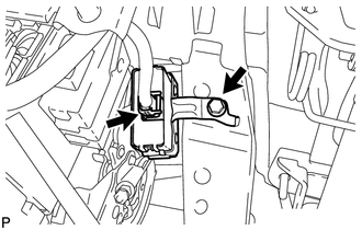
(b) Remove the bolt and tire pressure warning ECU.

 Tire Pressure Warning Receiver(w/ Antenna)
Components
COMPONENTS
ILLUSTRATION
Removal
REMOVAL
PROCEDURE
1. REMOVE ROOF HEADLINING ASSEMBLY
(a) Remove the roof headlining assembly (See page
).
2. REMOVE TIRE PRESSURE WARNING ANT ...
Other materials about Toyota 4Runner:
Rear No. 1 Seat Inner Belt Assembly(for 60/40 Split Double-folding Seat Type
Rh Side)
Components
COMPONENTS
ILLUSTRATION
Removal
REMOVAL
PROCEDURE
1. DISCONNECT REAR NO. 1 SEAT OUTER BELT ASSEMBLY RH
(a) Pull the rear seat cushion band, release the lock and lift up the
back of the seat cushion to rotate it forward.
...
On-vehicle Inspection
ON-VEHICLE INSPECTION
CAUTION / NOTICE / HINT
HINT:
Use the same procedure for the RH and LH sides.
The procedure listed below is for the LH side.
PROCEDURE
1. CHECK SIDE AIRBAG SENSOR ASSEMBLY LH (VEHICLE NOT INVOLVED IN COLLISION)
(a) ...
0.0067