Toyota 4Runner: Tire Pressure Warning Receiver(w/ Antenna)
Components
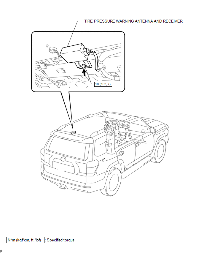
COMPONENTS
ILLUSTRATION
Removal
REMOVAL
PROCEDURE
1. REMOVE ROOF HEADLINING ASSEMBLY
(a) Remove the roof headlining assembly (See page
.gif) ).
).
2. REMOVE TIRE PRESSURE WARNING ANTENNA AND RECEIVER
|
(a) Disconnect the connector. |
|
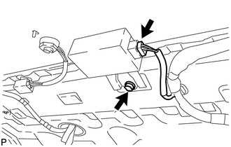
(b) Remove the bolt and receiver assembly.
Installation
INSTALLATION
PROCEDURE
1. INSTALL TIRE PRESSURE WARNING ANTENNA AND RECEIVER
(a) Install the receiver assembly with the bolt.
Torque:
10 N·m {102 kgf·cm, 7 ft·lbf}
(b) Connect the connector.
2. INSTALL ROOF HEADLINING ASSEMBLY
(a) Install the roof headlining assembly (See page
.gif) ).
).
3. PERFORM REGISTRATION OF TRANSMITTER ID
(a) Perform registration of the transmitter ID (See page
).
 Tire Pressure Warning Ecu
Components
COMPONENTS
ILLUSTRATION
Installation
INSTALLATION
PROCEDURE
1. INSTALL TIRE PRESSURE WARNING ECU
(a) Install the tire pressure warning ECU with the bolt.
Torque:
5.5 N·m {5 ...

Other materials about Toyota 4Runner:
Front Clearance Sonar Sensor RH Circuit
DESCRIPTION
The ultrasonic sensor sends and receives ultrasonic waves. Based on the received
wave, the sensor calculates the approximate distance between the vehicle and the
obstacle, and sends the distance value as a signal to the clearance warning ECU
...
Terminals Of Ecu
TERMINALS OF ECU
1. CHECK OCCUPANT CLASSIFICATION ECU
Terminal No. (Symbol)
Wiring Color
Terminal Description
Condition
Specified Condition
a9-1 (+B) - a9-3 (GND)
W - W-B
...
0.0078