Toyota 4Runner: Torque Converter Clutch Pressure Control Solenoid Performance (Shift Solenoid Valve SLU) (P2757)
DESCRIPTION
The ECM uses the signals from the throttle position sensor, air-flow meter, turbine (input) speed sensor, output speed sensor and crankshaft position sensor to monitor the engagement condition of the lock-up clutch.
Then the ECM compares the engagement condition of the lock-up clutch with the lock-up schedule in the ECM memory to detect mechanical problems of the shift solenoid valve SLU, valve body and torque converter.
|
DTC Code |
DTC Detection Condition |
Trouble Area |
|---|---|---|
|
P2757 |
Lock-up does not occur when driving in the lock-up range (normal driving at 80 km/h (50 mph)), or lock-up remains ON in the lock-up OFF range (2-trip detection logic). |
|
MONITOR DESCRIPTION
Torque converter lock-up is controlled by the ECM based on the turbine (input) speed sensor NT, output speed sensor SP2, engine speed, engine load, engine temperature, vehicle speed, transmission temperature and gear selection. The ECM determines the lock-up status of the torque converter by comparing the engine speed (NE) to the input turbine speed (NT). The ECM calculates the actual transmission gear by comparing input turbine speed (NT) to output shaft speed (SP2). When conditions are appropriate, the ECM requests "lock-up" by applying control voltage to shift solenoid SLU. When SLU is turned on, it applies pressure to the lock-up relay valve and locks the torque converter.
If the ECM detects no lock-up after lock-up has been requested or if it detects lock-up when it is not requested, the ECM interprets this as a fault in the shift solenoid valve SLU or lock-up system performance.
The ECM will turn on the MIL and store the DTC.
Example:
When either of the following is met, the system judges it as a malfunction.
- There is a difference in speed between the input side (engine speed) and output side (input turbine speed) of the torque converter when the ECM commands lock-up (Engine speed is at least 70 rpm more than input turbine speed.)
- There is no difference in speed between the input side (engine speed)
and output side (input turbine speed) of the torque converter when the ECM
commands lock-up off.
The difference between engine speed and input turbine speed is less than 35 rpm.
MONITOR STRATEGY
|
Related DTCs |
P2757: Shift solenoid valve SLU/Functional check |
|
Required sensors/Components |
Shift solenoid valve SLU, Valve body, Vehicle speed sensor, Speed sensor (NT), Speed sensor (NO), Throttle position sensor |
|
Frequency of operation |
Continuous |
|
Duration |
OFF malfunction (A) 2 sec. OFF malfunction (B) 0.4 sec. ON malfunction 1.8 sec. |
|
MIL operation |
2 driving cycles |
|
Sequence of operation |
None |
TYPICAL ENABLING CONDITIONS
All|
The monitor will run whenever the following DTCs are not stored |
P0717 (Turbine speed sensor circuit) P0722 (Output speed sensor circuit) P0751, P0973, P0974 (Shift solenoid valve S1 circuit) P0756, P0976, P0977 (Shift solenoid valve S2 circuit) P0985, P0986 (Shift solenoid valve SR circuit) P2759 (Shift solenoid valve SLU circuit) P0327, P0328, P0332, P0333 (KCS sensor circuit) P0776 (Shift solenoid valve SL2 circuit) P0781 (1-2 shift valve) |
|
ETCS (Electric Throttle Control System) |
Not system down |
|
Transmission position |
"D" |
|
Duration time from shifting "N" to "D" |
4 sec. or more |
|
ECT |
40°C (104°F) or higher |
|
Spark advance from max. retard timing by KCS control |
0° crankshaft angle or more |
|
Engine |
Starting |
|
ECM selected gear |
2nd, 3rd, 4th or 5th |
|
Vehicle speed |
25 km/h (15.5 mph) or more |
|
ECM lock-up command |
ON (SLU pressure: 513 kPa (5.2 kgf/cm2, 74 psi) or higher) |
|
Duration time from lock-up on command |
3 sec. or more |
|
Turbine speed/Output speed (NT/NO) |
0.65 or more, and 0.79 or less |
|
Calculated load value |
25.2% or more at 1000 rpm (Conditions vary with turbine speed) |
|
Vehicle speed |
Less than 120 km/h (74.6 mph) |
|
ECM selected gear |
2nd |
|
Duration time from shift command of ECM |
2 sec. or more |
|
Vehicle speed |
2 km/h (1.2 mph) or more |
|
Output speed |
2nd → 1st down shift point or more |
|
Throttle valve opening angle |
6.5% or more at 2000 rpm (Conditions varies with engine speed) |
|
Calculated load value |
7.75% or more |
|
Following conditions is met: (a), (b), (c), (d) or (e) |
- |
|
(a) Turbine speed/Output speed (NT/NO) |
3.30 or more, and 7.50 or less (This means actual gear is 1st) |
|
(b) Turbine speed/Output speed (NT/NO) |
1.91 or more, and 2.35 or less (This means actual gear is 2nd) |
|
(c) Turbine speed/Output speed (NT/NO) |
1.28 or more, and 1.53 or less (This means actual gear is 3rd) |
|
(d) Turbine speed/Output speed (NT/NO) |
0.93 or more, and 1.07 or less (This means actual gear is 4th) |
|
(e) Turbine speed/Output speed (NT/NO) |
0.65 or more, and 0.79 or less (This means actual gear is 5th) |
|
ECM lock-up command |
OFF (SLU pressure: below 4 kPa (0.04 kgf/cm2, 0.6 psi)) |
|
Duration time from lock-up off command |
3 sec. or more |
|
Following conditions is met: (a), (b), (c) or (d) |
- |
|
(a) Turbine speed/Output speed (NT/NO) |
1.91 or more, and 2.35 or less (This means actual gear is 2nd) |
|
(b) Turbine speed/Output speed (NT/NO) |
1.28 or more, and 1.53 or less (This means actual gear is 3rd) |
|
(c) Turbine speed/Output speed (NT/NO) |
0.93 or more, and 1.07 or less (This means actual gear is 4th) |
|
(d) Turbine speed/Output speed (NT/NO) |
0.65 or more, and 0.79 or less (This means actual gear is 5th) |
|
Throttle valve opening angle |
7% or more |
|
Calculated load value |
25.2% or more at 1000 rpm (Conditions vary with turbine speed) |
|
Vehicle speed |
Less than 120 km/h (74.6 mph) |
TYPICAL MALFUNCTION THRESHOLDS
- Both of the following conditions are met: OFF malfunction (A) and (B)
|
Engine speed - Turbine speed (NE - NT) |
70 rpm or more |
|
Turbine speed/Output speed (NT/NO) |
Less than 3.30, or more than 7.50 |
- 2 detections are necessary per driving cycle:
- 1st detection: temporary flag ON
- 2nd detection: pending fault code ON
- Vehicle speed must be under 10 km/h (6.2 mph) once before 2nd detection.
|
Engine speed - Turbine speed (NE - NT) |
Less than 35 rpm |
CAUTION / NOTICE / HINT
NOTICE:
Perform the universal trip to clear permanent DTCs (See page
.gif) ).
).
1. ACTIVE TEST
HINT:
Using the Techstream to perform Active Tests allows relays, VSVs, actuators and other items to be operated without removing any parts. This non-intrusive functional inspection can be very useful because intermittent operation may be discovered before parts or wiring is disturbed. Performing Active Tests early in troubleshooting is one way to save diagnostic time. Data List information can be displayed while performing Active Tests.
(a) Warm up the engine.
(b) Turn the ignition switch off.
(c) Connect the Techstream to the DLC3.
(d) Turn the ignition switch to ON.
(e) Turn the Techstream on.
(f) Enter the following menus: Powertrain / Engine and ECT / Active Test.
(g) According to the display on the Techstream, perform the Active Test.
Engine and ECT|
Tester Display |
Test Part |
Control Range |
Diagnostic Note |
|---|---|---|---|
|
Activate the Lock Up |
Control shift solenoid SLU to set automatic transmission to lock-up |
ON or OFF |
Possible to check shift solenoid valve SLU operation. [Vehicle Condition]
|
HINT:
- This test can be conducted when the vehicle speed is 80 km/h (50 mph) or more.
- This test can be conducted in 5th gear.
(h) Lightly depress the accelerator pedal and check that the engine speed does not change abruptly.
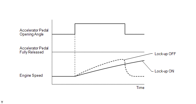
HINT:
- When changing the accelerator pedal opening angle while driving, if the engine speed does not change, lock-up is on.
- Slowly release the accelerator pedal in order to decelerate, but do not fully release the pedal. (Fully releasing the pedal will close the throttle valve and lock-up may be turned off automatically.)
PROCEDURE
|
1. |
CHECK DTC OUTPUT (IN ADDITION TO DTC P2757) |
(a) Connect the Techstream to the DLC3.
(b) Turn the ignition switch to ON.
(c) Turn the Techstream on.
(d) Enter the following menus: Powertrain / Engine and ECT / Trouble Codes.
(e) Read the DTCs using the Techstream.
Result|
Result |
Proceed to |
|---|---|
|
Only P2757 is output |
A |
|
P2757 and other DTCs are output |
B |
HINT:
If any other codes besides P2757 are output, perform troubleshooting for those DTCs first.
| B | .gif) |
GO TO DTC CHART |
|
.gif)
|
2. |
INSPECT SHIFT SOLENOID VALVE SLU |
|
(a) Remove shift solenoid valve SLU. |
|
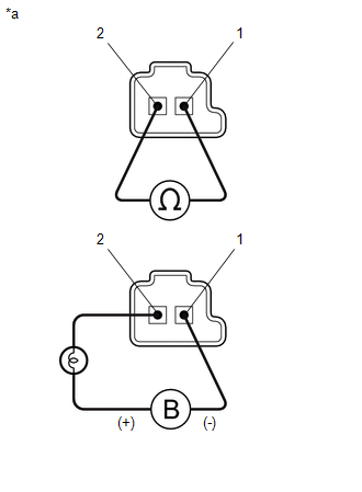
(b) Measure the resistance according to the value(s) in the table below.
Standard Resistance:
|
Tester Connection |
Condition |
Specified Condition |
|---|---|---|
|
1 - 2 |
20°C (68°F) |
5.0 to 5.6 Ω |
(c) Apply 12 V battery voltage to the shift solenoid valve and check that the valve moves and makes an operating noise.
OK:
|
Measurement Condition |
Specified Condition |
|---|---|
|
Valve moves and makes operating noise |
|
*a |
Component without harness connected (Shift Solenoid Valve SLU) |
| NG | |
REPLACE SHIFT SOLENOID VALVE SLU |
|
|
3. |
INSPECT TRANSMISSION VALVE BODY ASSEMBLY |
| NG | |
REPAIR OR REPLACE TRANSMISSION VALVE BODY ASSEMBLY |
|
|
4. |
INSPECT TORQUE CONVERTER ASSEMBLY |
| OK | |
REPAIR OR REPLACE AUTOMATIC TRANSMISSION ASSEMBLY |
| NG | |
REPLACE TORQUE CONVERTER ASSEMBLY |
 Torque Converter Clutch Pressure Control Solenoid Control Circuit Electrical
(Shift Solenoid Valve SLU) (P2759)
Torque Converter Clutch Pressure Control Solenoid Control Circuit Electrical
(Shift Solenoid Valve SLU) (P2759)
DESCRIPTION
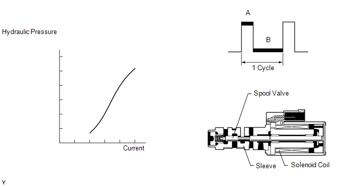
The amount of current flow to the solenoid is controlled by the duty ratio* of
the ECM output signal. During the lock-up operation, if the duty ratio increases,
the lock-up hydraulic ...
 Transmission Fluid Temperature Sensor "B" Circuit Low Input (P2742,P2743)
DESCRIPTION
The Automatic Transmission Fluid (ATF) temperature sensor is on the transmission,
just in front of the oil cooler inlet pipeline.
If the ECM detects an abnormally high ATF temperature ...
Other materials about Toyota 4Runner:
Inspection
INSPECTION
PROCEDURE
1. TRANSFER SYSTEM
NOTICE:
To shift from H2 to H4, move the transfer shift lever while keeping
the wheels facing straight ahead.
To shift from H4 to L4, stop the vehicle, move the shift lever to N
and then move the ...
How To Proceed With Troubleshooting
CAUTION / NOTICE / HINT
HINT:
Use the following procedure to troubleshoot the navigation system.
*: Use the Techstream.
PROCEDURE
1.
VEHICLE BROUGHT TO WORKSHOP
NEXT
...
0.0259