Toyota 4Runner: Transmission Control Switch Circuit
DESCRIPTION
After moving the shift lever to S, it is possible to switch the shift range between "1" (S1 range) and "5" (S5 range) using the transmission control switch.
Shifting to "+" once raises the shift range by one, and shifting to "-" once lowers the shift range by one.
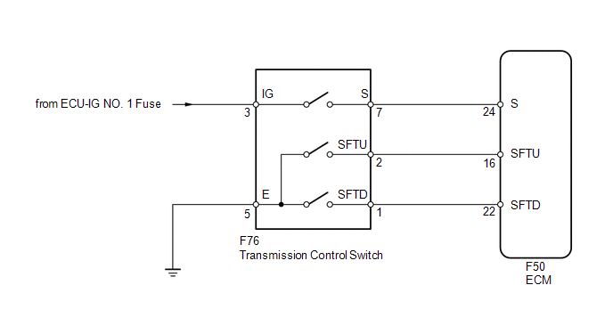
WIRING DIAGRAM
PROCEDURE
|
1. |
INSPECT TRANSMISSION CONTROL SWITCH |
|
(a) Disconnect the F76 transmission control switch connector. |
|
(b) Measure the resistance according to the value(s) in the table below.
Standard Resistance:
|
Tester Connection |
Condition |
Specified Condition |
|---|---|---|
|
3 (IG) - 7 (S) |
Shift lever in S, "+" or "-" |
Below 1 Ω |
|
2 (SFTU) - 5 (E) |
Shift lever held in "+" (Up-shift) |
Below 1 Ω |
|
1 (SFTD) - 5 (E) |
Shift lever held in "-" (Down-shift) |
Below 1 Ω |
|
3 (IG) - 7 (S) |
Shift lever not in S, "+" or "-" |
10 kΩ or higher |
|
2 (SFTU) - 5 (E) |
Shift lever in S |
10 kΩ or higher |
|
1 (SFTD) - 5 (E) |
Shift lever in S |
10 kΩ or higher |
|
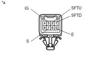
*a |
Component without harness connected (Transmission Control Switch) |
| NG | .gif) |
REPLACE TRANSMISSION CONTROL SWITCH (TRANSMISSION FLOOR SHIFT ASSEMBLY) |
|
.gif)
|
2. |
CHECK HARNESS AND CONNECTOR (TRANSMISSION CONTROL SWITCH - BATTERY, BODY GROUND) |
|
(a) Disconnect the F76 transmission control switch connector. |
|
(b) Measure the voltage according to the value(s) in the table below.
Standard Voltage:
|
Tester Connection |
Switch Condition |
Specified Condition |
|---|---|---|
|
F76-3 (IG) - Body ground |
Ignition switch ON |
11 to 14 V |
|
F76-3 (IG) - Body ground |
Ignition switch off |
Below 1 V |
(c) Turn the ignition switch off.
(d) Measure the resistance according to the value(s) in the table below.
Standard Resistance:
|
Tester Connection |
Condition |
Specified Condition |
|---|---|---|
|
F76-5 (E) - Body ground |
Always |
Below 1 Ω |
|
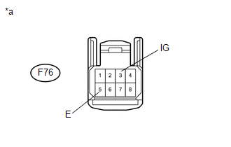
*a |
Front view of wire harness connector (to Transmission Control Switch) |
| NG | |
REPAIR OR REPLACE HARNESS OR CONNECTOR |
|
|
3. |
CHECK HARNESS AND CONNECTOR (TRANSMISSION CONTROL SWITCH - ECM) |
|
(a) Disconnect the F50 ECM connector. |
|
(b) Measure the voltage according to the value(s) in the table below.
Standard Voltage:
|
Tester Connection |
Condition |
Specified Condition |
|---|---|---|
|
F50-24 (S) - Body ground |
|
11 to 14 V |
|
F50-24 (S) - Body ground |
|
Below 1 V |
(c) Turn the ignition switch off.
(d) Measure the resistance according to the value(s) in the table below.
Standard Resistance:
|
Tester Connection |
Condition |
Specified Condition |
|---|---|---|
|
F50-16 (SFTU) - Body ground |
Shift lever held in "+" (Up-shift) |
Below 1 Ω |
|
F50-22 (SFTD) - Body ground |
Shift lever held in "-" (Down-shift) |
Below 1 Ω |
|
F50-16 (SFTU) - Body ground |
Shift lever in S |
10 kΩ or higher |
|
F50-22 (SFTD) - Body ground |
Shift lever in S |
10 kΩ or higher |
|
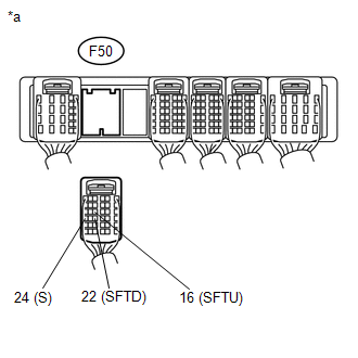
*a |
Rear view of wire harness connector (to ECM) |
| OK | |
PROCEED TO NEXT SUSPECTED AREA SHOWN IN PROBLEM SYMPTOMS TABLE |
| NG | |
REPAIR OR REPLACE HARNESS OR CONNECTOR |
 Transmission Fluid Temperature Sensor "A" Performance (P0711)
DESCRIPTION
The ATF (Automatic Transmission Fluid) temperature sensor converts the ATF temperature
into a resistance value which is input into the ECM.
The ECM applies a voltage to the temperature ...

Other materials about Toyota 4Runner:
Does not Play even after Bluetooth Audio Mode is Selected
CAUTION / NOTICE / HINT
NOTICE:
After replacing the navigation receiver assembly of vehicles subscribed to pay-type
satellite radio broadcasts, registration of the XM radio ID is necessary.
HINT:
Even if the portable player can play audio content, it may ...
Customization
Customizable features
Your vehicle includes a variety of electronic features that can be
personalized to suit your preferences. Programming these preferences requires
specialized equipment and may be performed by your Toyota dealer.
Some function setting ...
0.0072