Toyota 4Runner: 4wd Control Ecu
Components
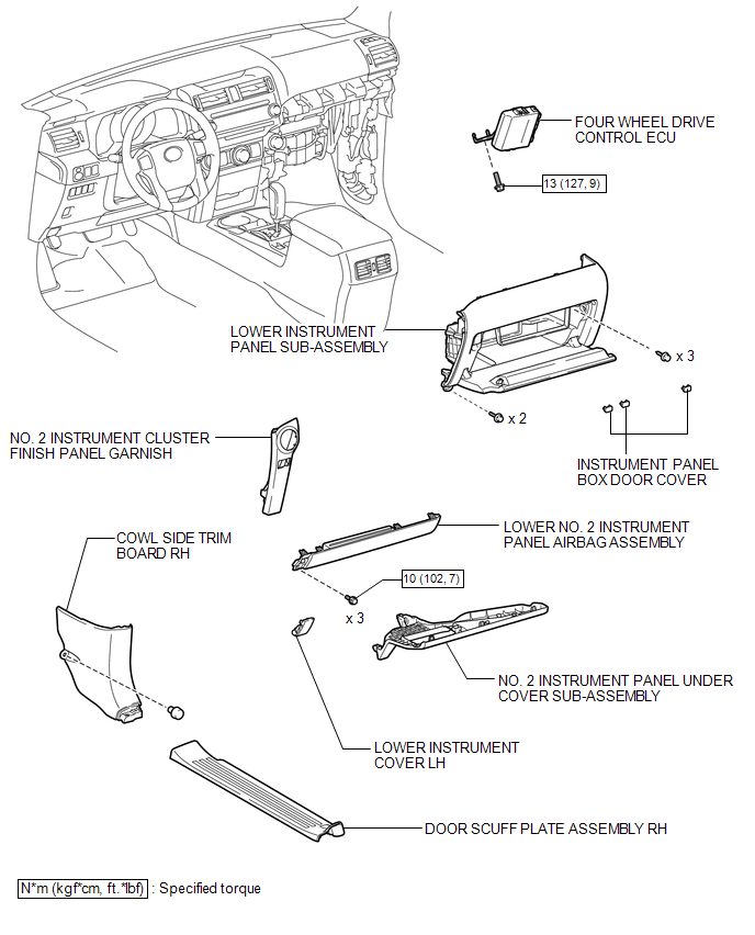
COMPONENTS
ILLUSTRATION
Removal
REMOVAL
PROCEDURE
1. REMOVE NO. 2 INSTRUMENT CLUSTER FINISH PANEL GARNISH
.gif)
2. REMOVE DOOR SCUFF PLATE ASSEMBLY RH
3. REMOVE COWL SIDE TRIM BOARD RH
4. REMOVE NO. 2 INSTRUMENT PANEL UNDER COVER SUB-ASSEMBLY
5. REMOVE LOWER INSTRUMENT COVER LH
6. REMOVE LOWER NO. 2 INSTRUMENT PANEL AIRBAG ASSEMBLY
7. REMOVE INSTRUMENT PANEL BOX DOOR COVER
8. REMOVE LOWER INSTRUMENT PANEL SUB-ASSEMBLY
9. REMOVE 4 WHEEL DRIVE CONTROL ECU NO.2
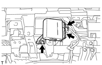
(a) Disconnect the 2 connectors.
(b) Remove the bolt and four wheel drive control ECU.
Installation
INSTALLATION
PROCEDURE
1. INSTALL 4 WHEEL DRIVE CONTROL ECU NO.2
(a) Install the four wheel drive control ECU with the bolt.
Torque:
13 N·m {127 kgf·cm, 9 ft·lbf}
(b) Connect the 2 connectors.
2. INSTALL LOWER INSTRUMENT PANEL SUB-ASSEMBLY
.gif)
3. INSTALL INSTRUMENT PANEL BOX DOOR COVER
4. INSTALL LOWER NO. 2 INSTRUMENT PANEL AIRBAG ASSEMBLY
5. INSTALL LOWER INSTRUMENT COVER LH
6. INSTALL NO. 2 INSTRUMENT PANEL UNDER COVER SUB-ASSEMBLY
7. INSTALL COWL SIDE TRIM BOARD RH
8. INSTALL DOOR SCUFF PLATE ASSEMBLY RH
9. INSTALL NO. 2 INSTRUMENT CLUSTER FINISH PANEL GARNISH


Other materials about Toyota 4Runner:
Auto Down Operation does not Fully Open Power Window (Catch Protection Function
is Activated)
DESCRIPTION
If any door glass or a power window regulator motor assembly does not operate
smoothly, the catch protection function may be triggered automatically, resulting
in the auto down operation being unable to fully open the power window.
CAUTION / ...
USB Device Malfunction (B1585)
DESCRIPTION
This DTC is stored when a malfunction occurs in a connected device.
DTC No.
DTC Detection Condition
Trouble Area
B1585
USB Device Malfunction
Non mass-storage class or inc ...

0.0233