Toyota 4Runner: Low Power Supply Voltage Malfunction (C1241)
DESCRIPTION
If the voltage supplied to the IG1 terminal is within the DTC detection range due to malfunctions in components such as the battery and generator circuit, this DTC is stored.
|
DTC Code |
DTC Detection Condition |
Trouble Area |
|---|---|---|
|
C1241 |
Either condition is met: 1. Both of the following conditions continue for at least 10 seconds.
2. All of the following conditions continue for at least 0.2 seconds.
|
|
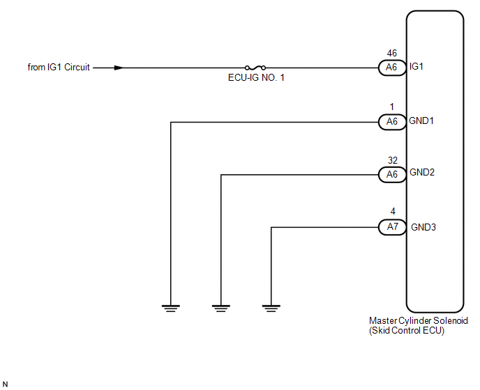
WIRING DIAGRAM
CAUTION / NOTICE / HINT
NOTICE:
- When replacing the master cylinder solenoid, perform calibration (See
page
.gif) ).
). - Inspect the fuses for circuits related to this system before performing the following inspection procedure.
PROCEDURE
|
1. |
READ VALUE USING TECHSTREAM (IG1 VOLTAGE VALUE) |
(a) Turn the ignition switch off.
(b) Connect the Techstream to the DLC3.
(c) Turn the ignition switch to ON.
(d) Turn the Techstream on.
(e) Start the engine.
(f) Enter the following menus: Chassis / ABS/VSC/TRAC / Data List.
ABS/VSC/TRAC|
Tester Display |
Measurement Item/Range |
Normal Condition |
Diagnostic Note |
|---|---|---|---|
|
IG1 Voltage Value |
IG1 voltage value/ Min.: 0.00 V, Max.: 20.00 V |
Ignition switch ON: 11 to 14 V |
- |
(g) Check the voltage output from the skid control ECU displayed on the Techstream.
OK:
The output voltage displayed on the Techstream is within 11 to 14 V.
| NG | .gif) |
GO TO STEP 3 |
|
.gif)
|
2. |
RECONFIRM DTC |
(a) Clear the DTCs (See page ).
(b) Turn the ignition switch off.
(c) Check if the same DTCs are output (See page
).
HINT:
Reinstall the sensors, connectors, etc. and restore the previous vehicle conditions before rechecking for DTCs.
Result|
Result |
Proceed to |
|---|---|
|
DTC is output |
A |
|
DTC is not output (When troubleshooting in accordance with Diagnostic Trouble Code Chart) |
B |
|
DTC is not output (When troubleshooting in accordance with Problem Symptoms Table) |
C |
| A | |
REPLACE MASTER CYLINDER SOLENOID |
| B | |
USE SIMULATION METHOD TO CHECK |
| C | |
PROCEED TO NEXT SUSPECTED AREA SHOWN IN PROBLEM SYMPTOMS TABLE |
|
3. |
CHECK TERMINAL VOLTAGE (IG1) |
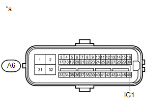
(a) Disconnect the A6 skid control ECU connector.
|
(b) Measure the voltage according to the value(s) in the table below. Standard Voltage:
|
|
| NG | |
REPAIR OR REPLACE HARNESS OR CONNECTOR |
|
|
4. |
CHECK HARNESS AND CONNECTOR (GND1, GND2 AND GND3 TERMINAL) |
| NG | |
REPAIR OR REPLACE HARNESS OR CONNECTOR |
|
|
5. |
RECONFIRM DTC |
(a) Clear the DTCs (See page ).
(b) Turn the ignition switch off.
(c) Check if the same DTCs are output (See page
).
HINT:
Reinstall the sensors, connectors, etc. and restore the previous vehicle conditions before rechecking for DTCs.
Result|
Result |
Proceed to |
|---|---|
|
DTC is output |
A |
|
DTC is not output (When troubleshooting in accordance with the Diagnostic Trouble Code Chart) |
B |
|
DTC is not output (When troubleshooting in accordance with the Problem Symptoms Table) |
C |
| A | |
REPLACE MASTER CYLINDER SOLENOID |
| B | |
USE SIMULATION METHOD TO CHECK |
| C | |
PROCEED TO NEXT SUSPECTED AREA SHOWN IN PROBLEM SYMPTOMS TABLE |
 Acceleration Sensor Stuck Malfunction (C1232,C1243,C1245,C1279)
DESCRIPTION
The skid control ECU receives signals from the yaw rate and acceleration sensor
via the CAN communication system.
If there is trouble in the bus lines between the yaw rate and accelera ...
 Open Circuit in IG1/IG2 Power Source Circuit (C1242)
DESCRIPTION
If there is a problem with the master cylinder solenoid (skid control ECU) power
supply circuit, the skid control ECU stores DTCs and prohibits operation under the
fail-safe function. ...
Other materials about Toyota 4Runner:
Generator Signal Circuit
DESCRIPTION
When the engine is started, the generator assembly turns on and a voltage pulse
signal is generated.
This signal is used by the air conditioning amplifier assembly.
The signal expressing the amount of output from the generator assembly is one ...
Adjustment
ADJUSTMENT
PROCEDURE
1. INSPECT PARKING BRAKE PEDAL TRAVEL
(a) Fully depress the parking brake pedal to engage the parking brake.
(b) Depress the pedal again to disengage the parking brake.
(c) Slowly depress the parking brake pedal using the specified fo ...

0.0262