Toyota 4Runner: Acceleration Sensor Stuck Malfunction (C1232,C1243,C1245,C1279)
DESCRIPTION
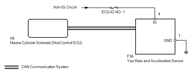
The skid control ECU receives signals from the yaw rate and acceleration sensor via the CAN communication system.
If there is trouble in the bus lines between the yaw rate and acceleration sensor and the CAN communication system, DTCs U0123 (yaw rate sensor communication trouble) and U0124 (acceleration sensor communication trouble) are stored.
|
DTC Code |
DTC Detection Condition |
Trouble Area |
|---|---|---|
|
C1232 |
At a vehicle speed of 10 km/h (6 mph) or more, the fluctuation range of the signal from one of either GL1 or GL2 is below 80 mV and the fluctuation range of the signal of the other is higher than 1.9 V for 30 seconds or more. |
|
|
C1243 |
The following condition repeats 16 times.
|
|
|
C1245 |
The following condition continues for at least 60 seconds.
|
|
|
C1279 |
Stored during test mode. |
WIRING DIAGRAM
CAUTION / NOTICE / HINT
NOTICE:
- When replacing the yaw rate and acceleration sensor, perform calibration
(See page
.gif) ).
). - Inspect the fuses for circuits related to this system before performing the following inspection procedure.
PROCEDURE
|
1. |
CHECK FOR DTC |
(a) Clear the DTCs (See page ).
(b) Turn the ignition switch off.
(c) Turn the ignition switch to ON.
(d) Check if DTCs U0073, U0123, C1210 and/or C1336 are output (See page
).
Result
|
Result |
Proceed to |
|---|---|
|
DTC U0073, U0123, C1210 and/or C1336 are not output |
A |
|
DTC U0073 and/or U0123 are output |
B |
|
DTC C1210 and/or C1336 are output |
C |
| B | .gif) |
GO TO CAN COMMUNICATION SYSTEM (HOW TO PROCEED WITH TROUBLESHOOTING) |
| C | |
REPAIR CIRCUIT INDICATED BY OUTPUT DTC |
|
.gif)
|
2. |
CHECK YAW RATE AND ACCELERATION SENSOR INSTALLATION |
(a) Check that the yaw rate and acceleration sensor is installed properly.
OK:
The sensor is tightened to the specified torque. The sensor is not tilted.
| NG | |
INSTALL YAW RATE AND ACCELERATION SENSOR CORRECTLY |
|
|
3. |
CHECK TERMINAL VOLTAGE AND RESISTANCE (IG, GND) |
(a) Disconnect the F36 yaw rate and acceleration sensor connector.
|
(b) Measure the voltage according to the value(s) in the table below. Standard Voltage:
|
|
(c) Measure the resistance according to the value(s) in the table below.
Standard Resistance:
|
Tester Connection |
Condition |
Specified Condition |
|---|---|---|
|
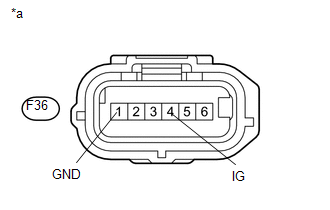
F36-1 (GND) - Body ground |
Always |
Below 1 Ω |
|
*a |
Front view of wire harness connector (to Yaw Rate and Acceleration Sensor) |
|
Result |
Proceed to |
|---|---|
|
OK (When troubleshooting in accordance with Diagnostic Trouble Code Chart) |
A |
|
OK (When troubleshooting in accordance with Problem Symptoms Table) |
B |
|
NG |
C |
| A | |
REPLACE YAW RATE AND ACCELERATION SENSOR |
| B | |
PROCEED TO NEXT SUSPECTED AREA SHOWN IN PROBLEM SYMPTOMS TABLE |
| C | |
REPAIR OR REPLACE HARNESS OR CONNECTOR |
 Zero Point Calibration of Yaw Rate Sensor Undone (C1210,C1336)
DESCRIPTION
The skid control ECU receives signals from the yaw rate and acceleration sensor
via the CAN communication system.
The yaw rate sensor has a built-in acceleration sensor and detects the ...
 Low Power Supply Voltage Malfunction (C1241)
DESCRIPTION
If the voltage supplied to the IG1 terminal is within the DTC detection range
due to malfunctions in components such as the battery and generator circuit, this
DTC is stored.
...
Other materials about Toyota 4Runner:
Air Mix Damper Control Servo Motor Circuit (Driver Side) (B1446/46)
DESCRIPTION
The damper servo sub-assembly (driver side air mix damper servo) sends pulse
signals to inform the No. 1 air conditioning amplifier assembly of the damper position.
The No. 1 air conditioning amplifier assembly activates the motor (normal or r ...
Removal
REMOVAL
PROCEDURE
1. DISCONNECT CABLE FROM NEGATIVE BATTERY TERMINAL
CAUTION:
Wait at least 90 seconds after disconnecting the cable from the negative (-)
battery terminal to disable the SRS system.
NOTICE:
When disconnecting the cable, some systems ne ...

0.0135