Toyota 4Runner: Air Conditioning Amplifier Communication Stop Mode
DESCRIPTION
|
Detection Item |
Symptom |
Trouble Area |
|---|---|---|
|
Air Conditioning Amplifier Communication Stop Mode |
Either condition is met:
|
|
HINT:
For vehicles without a smart key system only.
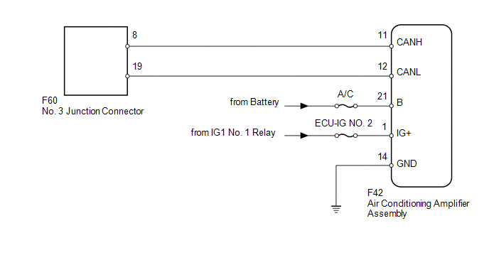
WIRING DIAGRAM
CAUTION / NOTICE / HINT
NOTICE:
Inspect the fuses for circuits related to this system before performing the following inspection procedure.
HINT:
Operating the ignition switch, any switches or any doors triggers related ECU and sensor communication with the CAN, which causes resistance variation.
PROCEDURE
|
1. |
DISCONNECT CABLE FROM NEGATIVE BATTERY TERMINAL |
(a) Disconnect the cable from the negative (-) battery terminal before measuring the resistances of the main wire and branch wire.
CAUTION:
Wait at least 90 seconds after disconnecting the cable from the negative (-) battery terminal to disable the SRS system.
NOTICE:
When disconnecting the cable, some systems need to be initialized after the cable
is reconnected (See page .gif) ).
).
|
.gif)
|
2. |
CHECK FOR OPEN IN CAN BUS WIRE (AIR CONDITIONING AMPLIFIER ASSEMBLY BRANCH WIRE) |
|
(a) Disconnect the F42 air conditioning amplifier assembly connector. |
|
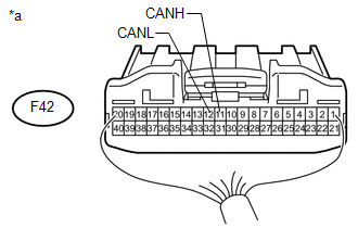
(b) Measure the resistance according to the value(s) in the table below.
Standard Resistance:
|
Tester Connection |
Switch Condition |
Specified Condition |
|---|---|---|
|
F42-11 (CANH) - F42-12 (CANL) |
Ignition switch off |
54 to 64 Ω |
|
*a |
Rear view of wire harness connector (to Air Conditioning Amplifier Assembly) |
| NG | .gif) |
REPAIR OR REPLACE AIR CONDITIONING AMPLIFIER ASSEMBLY BRANCH WIRE OR CONNECTOR (CANH, CANL) |
|
|
3. |
CHECK HARNESS AND CONNECTOR (AIR CONDITIONING AMPLIFIER ASSEMBLY - BATTERY AND BODY GROUND) |
|
(a) Connect the cable to the negative (-) battery terminal. NOTICE: When disconnecting the cable, some systems need to be initialized after
the cable is reconnected (See page |
|
(b) Measure the resistance according to the value(s) in the table below.
Standard Resistance:
|
Tester Connection |
Condition |
Specified Condition |
|---|---|---|
|
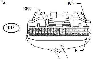
F42-14 (GND) - Body ground |
Always |
Below 1 Ω |
(c) Measure the voltage according to the value(s) in the table below.
Standard Voltage:
|
Tester Connection |
Switch Condition |
Specified Condition |
|---|---|---|
|
F42-21 (B) - Body ground |
Always |
11 to 14 V |
|
F42-1 (IG+) - Body ground |
Ignition switch ON |
11 to 14 V |
|
*a |
Rear view of wire harness connector (to Air Conditioning Amplifier Assembly) |
| OK | |
REPLACE AIR CONDITIONING AMPLIFIER ASSEMBLY |
| NG | |
REPAIR OR REPLACE HARNESS OR CONNECTOR |
 Skid Control ECU Communication Stop Mode
DESCRIPTION
Detection Item
Symptom
Trouble Area
Brake Actuator (Skid Control ECU) Communication Stop Mode
Either condition is met:
...
 Power Steering ECU Communication Stop Mode
DESCRIPTION
Detection Item
Symptom
Trouble Area
Power Steering ECU Communication Stop Mode
Either condition is met:
"PP ...
Other materials about Toyota 4Runner:
Downhill Assist Control Indicator Light does not Come ON
DESCRIPTION
Even if the downhill assist control switch is pressed, the downhill assist control
indicator light blinks and downhill assist control does not activate under the following
conditions:
The transfer is in H4.
The brake system is malf ...
Tire Pressure Warning Light Circuit
DESCRIPTION
If the tire pressure warning ECU detects a disconnected connector or an open
circuit between the tire pressure warning ECU and combination meter, the tire pressure
warning light turns off 10 seconds after the ignition switch is turned to ON, b ...

0.0275