Toyota 4Runner: Skid Control ECU Communication Stop Mode
DESCRIPTION
|
Detection Item |
Symptom |
Trouble Area |
|---|---|---|
|
Brake Actuator (Skid Control ECU) Communication Stop Mode |
Either condition is met:
|
|
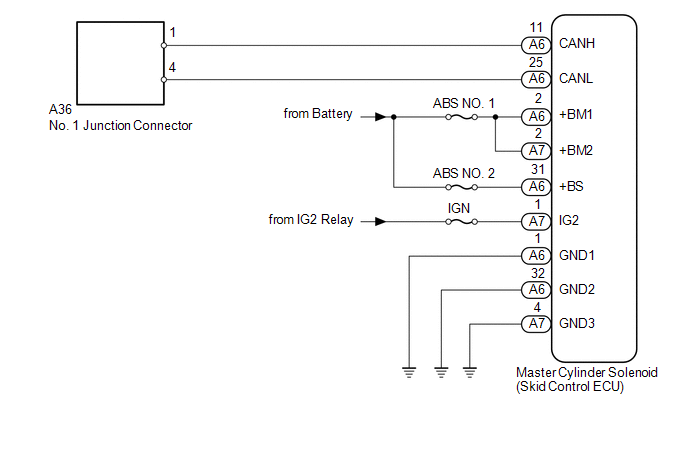
WIRING DIAGRAM
CAUTION / NOTICE / HINT
NOTICE:
Inspect the fuses for circuits related to this system before performing the following inspection procedure.
HINT:
Operating the ignition switch, any switches or any doors triggers related ECU and sensor communication with the CAN, which causes resistance variation.
PROCEDURE
|
1. |
DISCONNECT CABLE FROM NEGATIVE BATTERY TERMINAL |
(a) Disconnect the cable from the negative (-) battery terminal before measuring the resistances of the main wire and branch wire.
CAUTION:
Wait at least 90 seconds after disconnecting the cable from the negative (-) battery terminal to disable the SRS system.
NOTICE:
When disconnecting the cable, some systems need to be initialized after the cable
is reconnected (See page .gif) ).
).
|
.gif)
|
2. |
CHECK FOR OPEN IN CAN BUS WIRE (SKID CONTROL ECU BRANCH WIRE) |
|
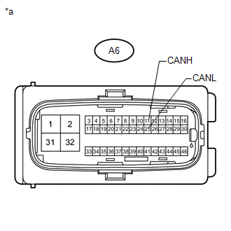
(a) Disconnect the A6 master cylinder solenoid (skid control ECU) connector. |
|
(b) Measure the resistance according to the value(s) in the table below.
Standard Resistance:
|
Tester Connection |
Switch Condition |
Specified Condition |
|---|---|---|
|
A6-11 (CANH) - A6-25 (CANL) |
Ignition switch off |
54 to 69 Ω |
|
*a |
Front view of wire harness connector (to Master Cylinder Solenoid [Skid Control ECU]) |
| NG | .gif) |
REPAIR OR REPLACE SKID CONTROL ECU BRANCH WIRE OR CONNECTOR (CANH, CANL) |
|
|
3. |
CHECK HARNESS AND CONNECTOR (SKID CONTROL ECU - BATTERY AND BODY GROUND) |
|
(a) Connect the cable to the negative (-) battery terminal. NOTICE: When disconnecting the cable, some systems need to be initialized after
the cable is reconnected (See page |
|
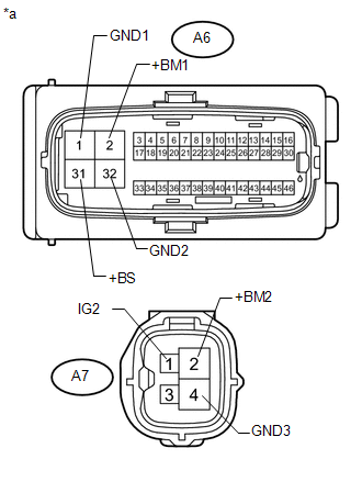
(b) Disconnect the A7 master cylinder solenoid (skid control ECU) connector.
(c) Measure the resistance according to the value(s) in the table below.
Standard Resistance:
|
Tester Connection |
Condition |
Specified Condition |
|---|---|---|
|
A6-1 (GND1) - Body ground |
Always |
Below 1 Ω |
|
A6-32 (GND2) - Body ground |
Always |
Below 1 Ω |
|
A7-4 (GND3) - Body ground |
Always |
Below 1 Ω |
(d) Measure the voltage according to the value(s) in the table below.
Standard Voltage:
|
Tester Connection |
Switch Condition |
Specified Condition |
|---|---|---|
|
A6-2 (+BM1) - Body ground |
Always |
11 to 14 V |
|
A7-2 (+BM2) - Body ground |
Always |
11 to 14 V |
|
A6-31 (+BS) - Body ground |
Always |
11 to 14 V |
|
A7-1 (IG2) - Body ground |
Ignition switch ON |
11 to 14 V |
|
*a |
Front view of wire harness connector (to Master Cylinder Solenoid [Skid Control ECU]) |
| OK | |
REPLACE MASTER CYLINDER SOLENOID |
| NG | |
REPAIR OR REPLACE HARNESS OR CONNECTOR |
 Brake Actuator (Skid Control ECU) Communication Stop Mode
DESCRIPTION
Detection Item
Symptom
Trouble Area
Brake Actuator (Skid Control ECU) Communication Stop Mode
Either condition is met:
...
 Air Conditioning Amplifier Communication Stop Mode
DESCRIPTION
Detection Item
Symptom
Trouble Area
Air Conditioning Amplifier Communication Stop Mode
Either condition is met:
...
Other materials about Toyota 4Runner:
Operation Check
OPERATION CHECK
1. CHECK INITIAL CHECK FUNCTION
(a) Check the initial check function for the buzzer.
(1) When the back sonar or clearance sonar switch assembly is turned on, check
that the following occurs: 1) after 0.2 seconds, the buzzer sounds for ap ...
Removal
REMOVAL
PROCEDURE
1. REMOVE ASSIST STRAP HOLE COVER
2. REMOVE ASSIST STRAP ASSEMBLY
3. REMOVE BACK DOOR TRIM PANEL ASSEMBLY
4. REMOVE MULTIPLEX NETWORK DOOR ECU
5. REMOVE NO. 2 BACK DOOR SERVICE HOLE COVER
6. REMOVE BACK DOOR LOCK CYLINDE ...

0.0096