Toyota 4Runner: Ambient Temperature Sensor Circuit (B1412)
DESCRIPTION
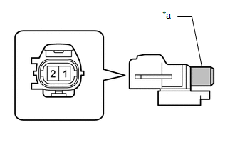
The cooler thermistor (ambient temperature sensor) is installed in the front part of the cooler condenser assembly. This sensor is connected to the air conditioning amplifier assembly and detects fluctuations in the ambient temperature. The sensor sends a signal to the air conditioning amplifier assembly. The resistance of the cooler thermistor (ambient temperature sensor) changes in accordance with the ambient temperature. As the temperature decreases, the resistance increases. As the temperature increases, the resistance decreases.
The air conditioning amplifier assembly applies a voltage (5 V) to the cooler thermistor (ambient temperature sensor) and reads voltage changes as changes in the resistance of the cooler thermistor (ambient temperature sensor).
|
DTC Code |
DTC Detection Condition |
Trouble Area |
|---|---|---|
|
B1412 |
An open or short in the cooler thermistor (ambient temperature sensor) circuit. |
|
WIRING DIAGRAM
.png)
PROCEDURE
|
1. |
READ VALUE USING TECHSTREAM (AMBIENT TEMPERATURE SENSOR) |
(a) Use the Data List to check if the cooler thermistor (ambient temperature
sensor) is functioning properly (See page .gif) ).
).
Air Conditioner
|
Tester Display |
Measurement Item/Range |
Normal Condition |
Diagnostic Note |
|---|---|---|---|
|
Ambient Temp Sensor |
Cooler thermistor (ambient temperature sensor) / Min: -23.3°C (-9.94°F) Max: 65.95°C (150.71°F) |
Actual ambient temperature displayed |
Open in the circuit: -23.3°C (-9.94°F). Short in the circuit: 65.95°C (150.71°F). |
OK:
The display is as specified in the normal condition column.
Result|
Result |
Proceed to |
|---|---|
|
OK (When troubleshooting according to problem symptoms table) |
A |
|
OK (When troubleshooting according to the DTC) |
B |
|
NG |
C |
| A | .gif) |
PROCEED TO NEXT SUSPECTED AREA SHOWN IN PROBLEM SYMPTOMS TABLE |
| B | |
REPLACE AIR CONDITIONING AMPLIFIER ASSEMBLY |
|
.gif)
|
2. |
INSPECT COOLER THERMISTOR (AMBIENT TEMPERATURE SENSOR) |
(a) Remove the cooler thermistor (ambient temperature sensor) (See page
).
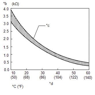
(b) Measure the resistance according to the value(s) in the table below.
Standard Resistance:
|
Tester Connection |
Condition |
Specified Condition |
|---|---|---|
|
1 - 2 |
10°C (50°F) |
3.00 to 3.73 kΩ |
|
15°C (59°F) |
2.45 to 2.88 kΩ |
|
|
20°C (68°F) |
1.95 to 2.30 kΩ |
|
|
25°C (77°F) |
1.60 to 1.80 kΩ |
|
|
30°C (86°F) |
1.28 to 1.47 kΩ |
|
|
35°C (95°F) |
1.00 to 1.22 kΩ |
|
|
40°C (104°F) |
0.80 to 1.00 kΩ |
|
|
45°C (113°F) |
0.65 to 0.85 kΩ |
|
|
50°C (122°F) |
0.50 to 0.70 kΩ |
|
|
55°C (131°F) |
0.44 to 0.60 kΩ |
|
|
60°C (140°F) |
0.36 to 0.50 kΩ |
|
*a |
Sensing Portion |
|
*b |
Resistance |
|
*c |
Allowable Range |
|
*d |
Temperature |
NOTICE:
- Even slightly touching the sensor may change the resistance value. Be sure to hold the connector of the sensor.
- When measuring, the sensor temperature must be the same as the ambient temperature.
HINT:
As the temperature increases, the resistance decreases (refer to the graph).
| NG | |
REPLACE COOLER THERMISTOR (AMBIENT TEMPERATURE SENSOR) |
|
|
3. |
CHECK HARNESS AND CONNECTOR (AMBIENT TEMPERATURE SENSOR - AIR CONDITIONING AMPLIFIER) |
(a) Disconnect the A23 sensor connector.
(b) Disconnect the F42 amplifier connector.
(c) Measure the resistance according to the value(s) in the table below.
Standard Resistance:
|
Tester Connection |
Condition |
Specified Condition |
|---|---|---|
|
A23-1 - F42-5 (TAM) |
Always |
Below 1 Ω |
|
A23-2 - F42-13 (SG-2) |
||
|
F42-5 (TAM) - Body ground |
Always |
10 kΩ or higher |
|
F42-13 (SG-2) - Body ground |
| OK | |
REPLACE AIR CONDITIONING AMPLIFIER ASSEMBLY |
| NG | |
REPAIR OR REPLACE HARNESS OR CONNECTOR |
 Dtc Check / Clear
DTC CHECK / CLEAR
1. CHECK FOR DTC
(a) Connect the Techstream to the DLC3.
(b) Turn the ignition switch to ON.
(c) Turn the Techstream on.
(d) Enter the following menus: Body Electrical / Air Con ...
 Diagnostic Trouble Code Chart
DIAGNOSTIC TROUBLE CODE CHART
HINT:
If a trouble code is output during the DTC check, inspect the trouble
areas listed for that code. For details of the code, refer to the "See page ...
Other materials about Toyota 4Runner:
Removal
REMOVAL
PROCEDURE
1. REMOVE JACK BOX HOLE COVER
2. REMOVE REAR QUARTER PANEL MUDGUARD LH
3. REMOVE REAR QUARTER PANEL MUDGUARD RH
HINT:
Use the same procedure as for the LH side.
4. REMOVE REAR BUMPER COVER
5. REMOVE NO. 3 FLOOR WIRE
6. RE ...
Inspection
INSPECTION
CAUTION / NOTICE / HINT
NOTICE:
Make sure that fingers or articles of clothing do not get caught in moving parts
when performing this test.
PROCEDURE
1. INSPECT WINDSHIELD WIPER MOTOR ASSEMBLY
(a) Check the LO operation.
(1) Co ...

0.0234